The short answer
Under 49 CFR 192.179(a) a gas transmission line must keep every point of pipe within 2.5 miles (4 km) of a sectionalizing block valve in a Class 4 location, 4 miles (6.4 km) in Class 3, 7.5 miles (12 km) in Class 2 and 10 miles (16 km) in Class 1. The rule measures the distance to a valve, not between valves, so the largest valve-to-valve gap that satisfies it is twice those numbers. Since 10 April 2023, any new or fully replaced onshore segment of 6 in or larger that triggers a valve must get a rupture-mitigation valve capable of closing within 30 minutes of rupture identification.
Two compressor stations, 40 miles of 30-inch pipe between them. Where the route crosses Class 1 farmland the design needs three intermediate block valves to hold every point of the line within ten miles of one. Where the same 40 miles passes through a town classified Class 3, the identical pipe needs nine. Same diameter, same grade, same MAOP, same wall thickness. The only thing that changed is how many buildings stand inside a 220-yard corridor along the centreline.
Valve spacing is the part of pipeline regulation that most technical pages dispose of in one sentence, and the part design packages most often get wrong in one cell of a spreadsheet. There are two reasons for that. The paragraph is written as a distance to the nearest valve rather than a distance between valves, which doubles the arithmetic error into a factor of two. And 192.179 contains a second, looser table that applies only to replacement projects — a table that never appears in the summary documents.
This page works through the section as written: the spacing table in both units, what a class location actually measures, the replacement exception, the 2023 rupture-mitigation valve mandate, and the blowdown requirement that sits in the same paragraph and is routinely forgotten.
The Spacing Table, in Miles and Kilometres
Paragraph (a) applies to transmission lines, offshore segments excluded. Its structure matters more than its numbers: it sets a maximum distance from each point on the pipeline to the nearest valve. That is not the same quantity as the gap between two valves.
| Class location | Max distance from any point to a valve — 192.179(a) | Valve-to-valve gap this permits |
|---|---|---|
| Class 4 | 2.5 mi (4.0 km) | up to 5 mi (8.0 km) |
| Class 3 | 4 mi (6.4 km) | up to 8 mi (12.9 km) |
| Class 2 | 7.5 mi (12 km) | up to 15 mi (24 km) |
| Class 1 | 10 mi (16 km) | up to 20 mi (32 km) |
| Offshore segments | Not in table (a) — see paragraph (d) | — |
The kilometre values are the ones printed in the regulation itself, not conversions added later. They are rounded: 2.5 miles is 4.02 km, 10 miles is 16.09 km. Use the mile figure when you are checking against the text and the kilometre figure when you are issuing a drawing; do not mix them across a document, because 7.5 miles and 12 km differ by 70 metres and a valve set at the wrong end of that difference will read as non-compliant on a third-party audit.
Two structural points hide inside that table. First, the values are maxima, not targets. Nothing prevents an operator from installing valves at half the permitted spacing, and many do on lines where a blowdown of the full permitted volume would take too long or vent too much gas. The rule sets a ceiling for public safety, not an optimum for operations.
Second, the table is applied point by point, not segment by segment. A 12-mile stretch of Class 1 pipe between two existing valves satisfies the rule if the midpoint is 6 miles from each end. A 25-mile stretch does not, even if a third valve sits somewhere in the middle, because the two spans either side of it would each have to be checked separately. The verification is a walk along the profile — every station, every road crossing, every class boundary — not a division of total length by ten.
What a Class Location Actually Is
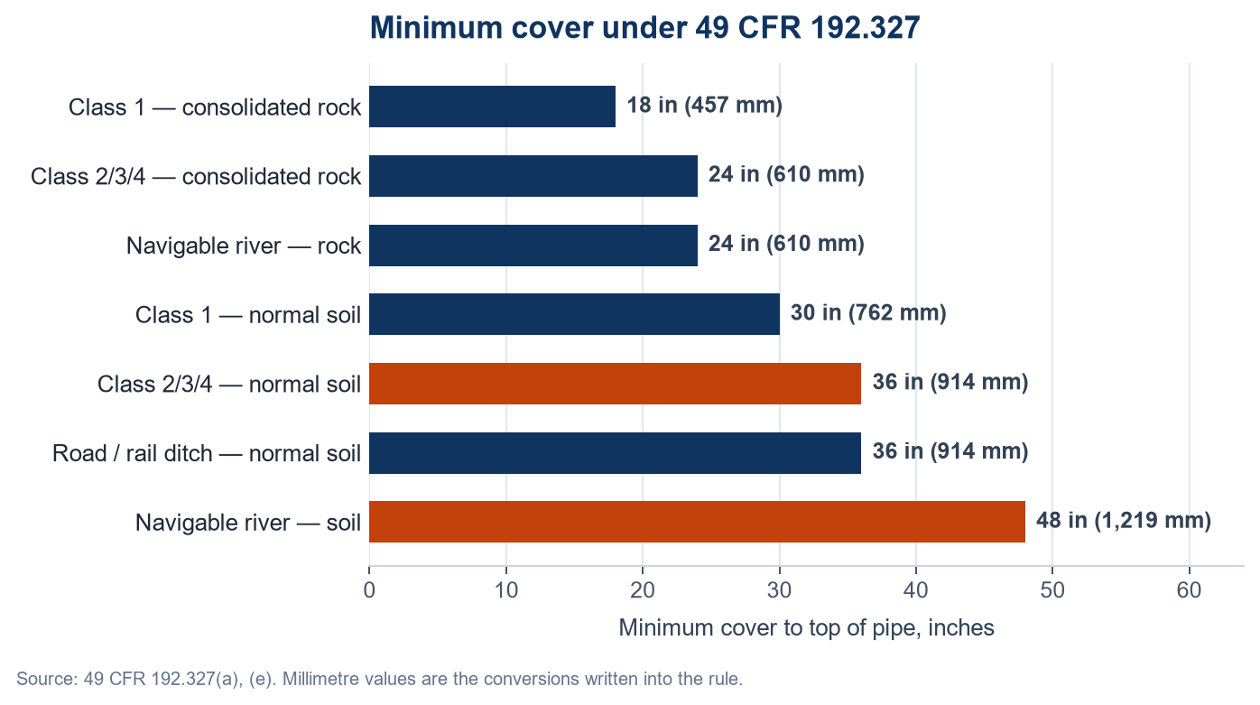
The class table in 192.5 is the input to everything else. It sets valve spacing here, the design factor in 192.111 (0.72, 0.60, 0.50, 0.40 for Classes 1 to 4), and the cover depth in 192.327. One building count therefore moves three requirements at once, which is why a class boundary is the most expensive line on a pipeline alignment sheet.
| Class | Buildings intended for human occupancy, per class location unit |
|---|---|
| Class 1 | 10 or fewer — and any offshore area is Class 1 regardless of count |
| Class 2 | More than 10 but fewer than 46 |
| Class 3 | 46 or more |
| Class 4 | Buildings of four or more storeys above ground are prevalent |
A class location unit is an onshore area extending 220 yards (200 m) on either side of the centreline of any continuous 1 mile (1.6 km) of pipeline. Both numbers are fixed and both are load-bearing. A housing estate 260 yards from the pipe contributes nothing to the count, however large it is. A dense strip of buildings along a 900-yard length does not form a unit of its own — the window is one mile long and slides along the line, so a cluster shorter than a mile is assessed inside whichever one-mile window contains the most of it.
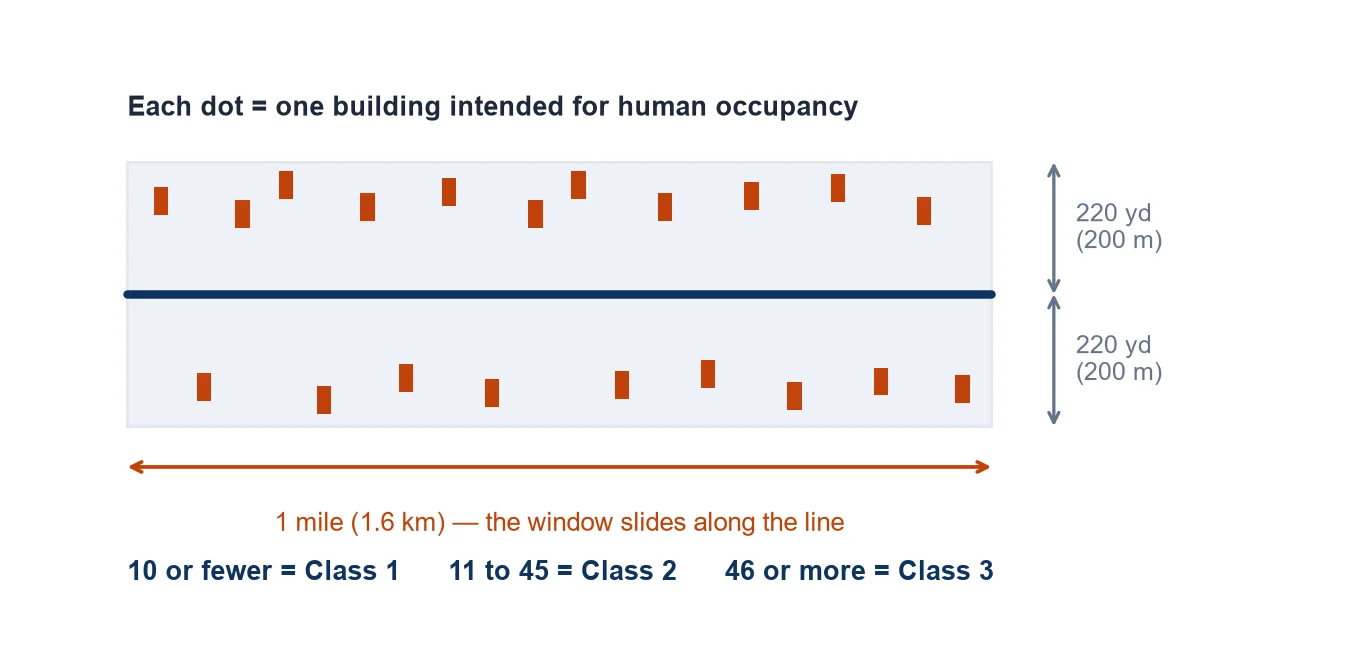
Each dwelling in a multi-unit building counts separately. A 60-unit apartment block is 60 buildings for this purpose, not one. That single sentence has pushed more suburban laterals from Class 1 into Class 3 than any other line in Part 192.
Class 3 has a second route in that is easy to miss. A location is Class 3 if the pipeline lies within 100 yards (91 m) of a building or a small, well-defined outside area — a playground, a recreation area, an outdoor theatre, a place of public assembly — that is occupied by 20 or more persons on at least 5 days a week for 10 weeks in any 12-month period. The days and weeks need not be consecutive. A school running five-day weeks for a ten-week term qualifies. There does not have to be a single house within the 220-yard corridor.
Class boundaries terminate at defined points rather than fading out. A Class 4 location ends 220 yards from the nearest building of four or more storeys. Where a cluster of buildings drives a Class 2 or Class 3 location, the class ends 220 yards from the nearest building in that cluster. Downstream of that point the line reverts to the class its own building count supports — which is why a valve placed just beyond a town boundary can sit in a 10-mile zone while the pipe 300 yards behind it was designed for 4 miles.
Distance to a Valve, Not Distance Between Valves
This is the error that shows up most often in third-party reviews. An engineer reads “4 miles in Class 3”, divides the segment length by four, rounds up, and produces a valve count. The regulation does not work that way.
Take a Class 3 run with two valves 8.0 miles apart. The midpoint is 4.0 miles from each end, so every point on the pipe is within 4 miles of a valve and the arrangement complies exactly. Stretch the same span to 8.2 miles and the midpoint is 4.1 miles from either valve. Every metre of that line is now non-compliant, and the fix is a new valve, not a paper adjustment.
The arithmetic consequence is that the design check is a maximum, not an average. On a profile, the usable valve-to-valve distance is twice the class value, but only where the class is constant across the whole span and both valves are proven operable. Where a class boundary falls inside a span, the two sides have to be checked against their own values, and the valve on the looser side is usually pulled towards the boundary to protect the stricter side. That is why valve stations so often sit a few hundred metres inside a town limit rather than at a round chainage.
Distance along the pipe is the working convention. 192.179 does not state a measurement method, and a straight-line reading would make no engineering sense for a rule aimed at limiting the volume of gas released from a ruptured segment — the quantity that matters is pipe length, not map distance. Treat that as the industry reading of the section, not as text quoted from it, and confirm the method with the operator or the authority having jurisdiction before it becomes an assumption in a design basis.
The Replacement Exception Most Designs Miss
Paragraph (h) was added by Amendment 192-130 in 2022 and it relaxes paragraph (a) for one situation only: pipe replacements on an existing pipeline. The condition is not the project type but the geometry — the exemption applies where the distance from every point on the replaced pipe to the nearest valve does not exceed the values below, and where the total spacing between valves stays inside the cap in the third column.
| Class | New pipe 192.179(a) |
Replacement 192.179(h) |
|---|---|---|
| Class 4 | 2.5 mi (4 km) | 4 mi (6.4 km) cap 8 mi |
| Class 3 | 4 mi (6.4 km) | 7.5 mi (12 km) cap 15 mi |
| Class 2 | 7.5 mi (12 km) | 10 mi (16 km) cap 20 mi |
| Class 1 | 10 mi (16 km) | 10 mi (16 km) cap 20 mi |
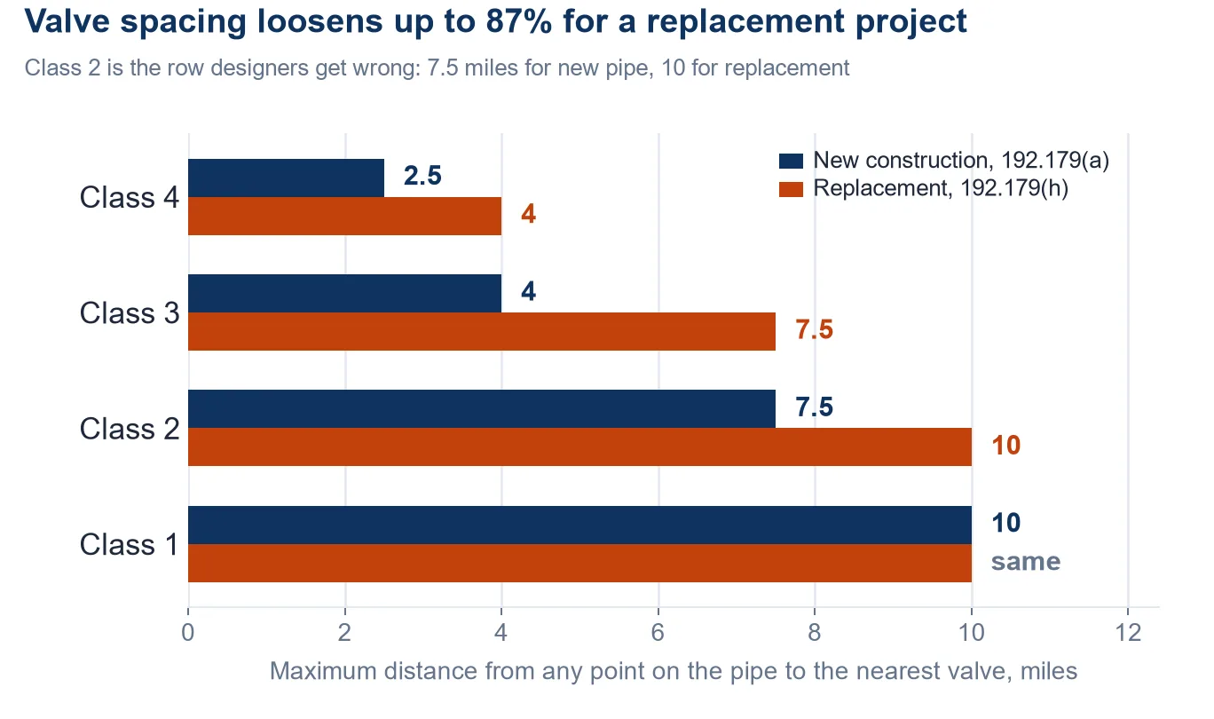
The Class 2 row is the one worth memorising. A replacement inside a Class 2 location is held to 10 miles, not 7.5. A Class 3 replacement is held to 7.5 instead of 4, and a Class 4 replacement to 4 instead of 2.5. Class 1 is unchanged, and Class 1 and Class 2 share a single 10-mile value and a single 20-mile cap.
The practical effect is that a 1970s line whose valve stations were laid out to the standards of the day will usually pass a 192.179(h) check and fail a 192.179(a) check. Both readings are correct; they answer different questions. A replacement project is assessed against (h). New pipe, and any segment that is not a replacement within the meaning of the section, is assessed against (a).
What (h) does not relax is everything else. Paragraph (b) on accessibility and support, paragraph (c) on blowdown, and paragraphs (e) and (f) on rupture-mitigation valves all continue to apply to a replacement. Relaxed spacing is not relaxed equipment.
The 2023 Rupture-Mitigation Valve Rule
Paragraphs (e) and (f) are the reason valve station design changed after April 2023. For onshore transmission segments of 6 in diameter or greater, constructed after 10 April 2023, or for entirely replaced segments installed after that date, the operator must install a rupture-mitigation valve (RMV) or an alternative equivalent technology wherever a valve has to be installed to meet the spacing requirements.
The exemption is geometric rather than procedural: the requirement does not apply to segments whose potential impact radius, as defined in 192.903, is 150 feet or less, in either a Class 1 or a Class 2 location. PIR scales with diameter and pressure, so the exemption effectively covers small-diameter, lower-pressure rural pipe and very little else.
What an RMV has to do is set out in 192.636, and the numbers there are the ones that reach the procurement list:
- 30 minutes. After rupture identification, the operator must fully close the RMVs needed to limit the release as soon as practicable and in any case within 30 minutes.
- Monitoring. Valve status — open, closed, or partially closed — plus upstream and downstream pressure must be monitorable, remotely or by on-site personnel.
- Back-up power. Remote-control and automatic shut-off valves need a back-up source to keep SCADA or remote communications alive.
- Flow modelling. Before an automatic shut-off valve is used as an RMV, the operator must model flow for the shut-off segment and any feeding laterals, across the maximum, normal and any other conditions likely within a 15-month window, to show the valve closes within 30 minutes.
- Manual valves. Allowed as alternative equivalent technology, but the operating procedure must include assembly of personnel, collection of tools, driving time at posted speed limits under heavy traffic, walking time to the valve, and the time to close every valve — all inside 30 minutes.
Use of alternative equivalent technology requires notification to PHMSA under 192.18 with a technical and safety evaluation attached. A manual compressor-station valve at a continuously manned station can be used without notification, provided it meets 192.636.
The procurement consequence is that a block valve on a post-2023 transmission line is not a valve any more. It is a valve plus actuator plus power plus communications plus a modelled closure time, and the specification has to be written for the assembly rather than the body.
Blowdown Valves and the Rest of 192.179
Paragraph (c) requires a blowdown valve on every section of transmission line between main line valves, sized to blow the section down as rapidly as practicable. There is no numeric rate in the text, which makes it the clause most likely to be argued about at commissioning — the capacity has to be defended against the segment volume, not against a table.
The discharge point carries its own requirement: located so the gas can be blown to atmosphere without hazard, and where the line runs alongside an overhead electric line, directed away from the conductors. On a route that parallels a transmission line for miles, that single sentence dictates which side of the right-of-way the blowdown stack faces.
Paragraph (b) covers the valve itself. It must be readily accessible, protected from tampering and damage, and supported so that neither the valve settles nor the pipe attached to it moves. Settlement is the failure mode that shows up years later as a leaking flange or a cracked weld at a valve bypass, and it starts with a valve set on a pad that was never designed for the weight of the assembly.
Paragraph (d) covers offshore segments, which must be equipped with valves or other components capable of shutting off flow to a platform in an emergency. Offshore segments are excluded from the spacing table in (a) but not from the shutdown requirement.
Why Distribution Lines Have No Table
Nothing in 192.179 applies to a distribution system. Section 192.181 governs, and it contains no distances at all. A high-pressure distribution system must have valves spaced so as to reduce the time to shut down a section of main in an emergency, with the spacing determined by operating pressure, main size and local physical conditions.
Three requirements do survive in usable form. A regulator station controlling flow or pressure must have a valve on the inlet piping, set far enough from the station that it can still be operated in an emergency that blocks access to the station. Every valve installed for operating or emergency purposes must sit in a readily accessible location with its stem or mechanism accessible. And a valve in a buried box or enclosure must be installed so the box does not transmit external loads to the main.
The distinction matters when a specification is being assembled. A line that is transmission upstream of a city gate and distribution downstream is two regulatory objects with two valve philosophies on the same drawing set. Quoting 192.179 against the distribution side is a common and expensive mistake: it produces valve stations the code does not require and leaves the actual requirement — operability in an emergency — unaddressed.
What This Means for the Pipe and the Valve
Four details follow from the sections above and belong in the technical specification rather than the alignment sheet.
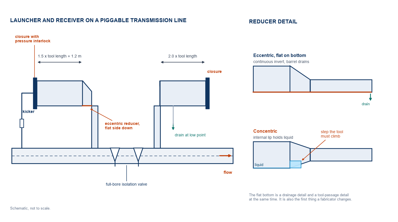
Full bore, because pigs have to pass. A sectionalizing valve sits in a line that will be inspected by in-line tools. A reduced-bore valve creates a trap for the tool and a pressure drop for the operator. Full-bore ball valves are the default on transmission lines for that reason, and the pig-trap and launcher design assumes it.
Welded, because flanges leak. Buried high-pressure transmission valves are welded into the line. A flanged joint in a valve station is an accessible leak path that nobody will inspect for twenty years.
Separately supported, because the soil will move. Paragraph (b)(2) is two sentences long and it drives the foundation design. A valve plus actuator on a 30-inch line is several tonnes of eccentric load on a pipe that was stress-analysed as a buried cylinder.
The class boundary is also a wall-thickness decision. The same 192.5 count that sets valve spacing sets the design factor in 192.111 — 0.72 in Class 1, 0.60 in Class 2, 0.50 in Class 3, 0.40 in Class 4. For a fixed diameter and MAOP, crossing into a higher class thickens the wall. On a route where a town sits midway, the valve count and the wall schedule change together, and the pup joints either side of each valve are where the two schedules meet.
The pipe that spans those valves is line pipe to API 5L, ordered in PSL2 for transmission service with the toughness and NDT regime that goes with it. The valve spacing rule does not change the pipe specification directly — it changes how many times the specification restarts along the route.
Frequently Asked Questions
Is the ten-mile Class 1 limit a maximum or a design target?
A maximum. The section sets a ceiling on the volume that can be isolated and blown down in one event; it does not set an optimum. Operators regularly install valves closer than the rule requires where a shorter section reduces venting time, limits the affected population, or shortens a repair. A design that sits exactly on the limit in every class is compliant and is rarely what an operator builds.
Can one valve serve the two segments on either side of it?
Yes, and that is the normal arrangement. The rule is written as a distance to the nearest valve, so a valve at a segment boundary satisfies both sides at once. What it does not do is let you average: each side has to be checked against its own class value independently.
Is the distance measured along the pipe or in a straight line?
192.179 does not specify. The working convention is length along the pipeline centreline, because the purpose of the rule is to bound the gas volume released from a ruptured segment, and that volume scales with pipe length rather than map distance. Confirm the method with the operator or the authority having jurisdiction rather than treating it as settled text.
What counts as a rupture-mitigation valve?
192.3 defines it as a valve capable of closing automatically or being closed remotely in a rupture, and 192.636 sets out what it has to be able to do: close fully within 30 minutes of rupture identification, be monitorable for position and for upstream and downstream pressure, and hold communications on back-up power. Remote-control valves, automatic shut-off valves and, with a PHMSA notification, manual valves can all qualify.
Does a valve station need a pig trap?
Not by rule. 192.179 says nothing about pig traps. What it does require, through the operating logic of the line, is that valves pass inspection tools, which is why transmission valves are specified full bore. Launcher and receiver stations are placed for inspection intervals and hydraulic reasons, not to satisfy the valve spacing clause.
Does a higher class location change the pipe grade?
No. It changes the design factor applied to the grade, which for a fixed diameter and pressure changes the required wall thickness. A Class 3 section of the same line as a Class 1 section will usually carry a heavier wall in the same grade rather than a higher grade in the same wall. That is a purchasing decision made at the mill, and it is decided by the building count on the alignment sheet.
Related Reading
- Pig launcher and receiver design — where the inspection tool enters and leaves the line, and what 49 CFR 192.150 asks of the trap
- Natural gas pipeline spacing requirements — the horizontal clearances to buildings, roads and buried services that sit alongside valve spacing on the same alignment sheet
- How deep a gas pipeline has to be buried — 49 CFR 192.327 cover depth by class, the other requirement driven by the same building count
- Pipeline hydrotest pressure — how the strength test after construction is set, and why the mill test does not cover it
- API 5L line pipe grades, PSL1 and PSL2 — the pipe specification between the valves, including the PSL2 toughness and inspection regime
- Safety valves and pressure relief valves — the relief side of the same equipment package, to ASME and API 526