The short answer
Under 49 CFR 192.150(a), a new gas transmission line — and any replacement of line pipe, valve, fitting or other line component on one — must be designed and built so that an instrumented internal inspection device can pass through it, in accordance with NACE SP0102 section 7. The launcher and receiver are the two pieces of hardware that make that possible. Their barrel, reducer, closure and isolation valve are sized by the longest tool the operator intends to run, not by the line size. A launcher barrel is typically 1.5 times the tool length, a receiver 2.0 times, the barrel bore one nominal size above the line, and the closure is the only part of the assembly that can kill someone when it is opened against pressure.
There is no such thing as a standard pig trap. Two 16 in launchers built to the same drawing in the same shop can differ by two metres of barrel and 40 % of the cost, because one is sized for a 1.2 m foam swab and the other for a 3.6 m multi-module inspection tool with three bodies and two universal joints. The line size fixes almost nothing. The tool fixes everything.
That is also why the regulatory requirement is written as a capability rather than a dimension. 192.150 does not tell an operator how long a barrel must be or how tight a bend may be. It tells them the line must be able to accept an instrumented tool, and then points at NACE SP0102 for what that means in practice. Everything below is the translation layer between that sentence and a purchase order for steel.
What 192.150 Actually Requires
Paragraph (a) is one sentence and it carries two triggers. The first is each new transmission line. The second is broader: each replacement of line pipe, valve, fitting or other line component in a transmission line. A 300 m replacement section on a 1960s line is caught by the same paragraph as a greenfield project, which is why a repair job can suddenly need a launcher that the original line never had.
Paragraph (b) lists the exceptions, and they are worth reading before anyone orders a trap. Nine categories are carved out, and three of them account for most of the confusion in the field.
| Exemption under 192.150(b) | What it covers | Where buyers get it wrong |
|---|---|---|
| (1) Manifolds | Headers and valve manifolds at stations | A manifold is not a whole station; the run between the manifold and the trap is still line pipe |
| (2) Station piping | Compressor, meter and regulator station piping | The trap itself is usually at the station boundary, not “inside” the station |
| (5) Sizes with no commercially available tool | Small diameters where no ILI tool is sold | The test is commercial availability at the time of construction, not engineering preference |
| (6) Class 4 distribution-connected lines | Transmission lines operated with a distribution system in Class 4 | Class 4 is a small share of mileage; do not assume the exemption applies because the line is urban |
| (7) Offshore lines | Offshore transmission, with conditions above 10¾ in (273 mm) | Above 10¾ in, platform space or taps must be shown to be incompatible, not asserted |
| (8) Gathering lines | Gathering, including the large-diameter gathering now regulated under Part 192 | Gathering status is a determination, not a name on a drawing |
Paragraph (c) matters for contractors. If an emergency or a construction problem makes compliance impracticable, the operator may proceed without the capability — but must petition within 30 days of discovering the problem, and if the petition is denied, must modify the segment within one year. That one-year clock is the reason a “temporary” tight bend or a reduced-bore valve sometimes turns into a scheduled dig a year later. It is cheaper to build the capability in the first place.
The Four Dimensions That Set the Trap
Trap geometry comes from the tool, and the tool comes from the inspection contract. Once the operator has told the ILI vendor which anomaly types they need to resolve, the vendor returns a tool length, a tool outside diameter, a minimum bend radius, a minimum bore and a required launch and receive straight length. Those five numbers, not the pipeline’s nominal size, drive the fabrication drawing.
| Dimension | Typical rule | Why it is that number |
|---|---|---|
| Barrel bore | One nominal size above the line, minimum 2 in (50 mm) larger than the tool OD | The tool has to enter without shaving its cups or magnets on the reducer lip |
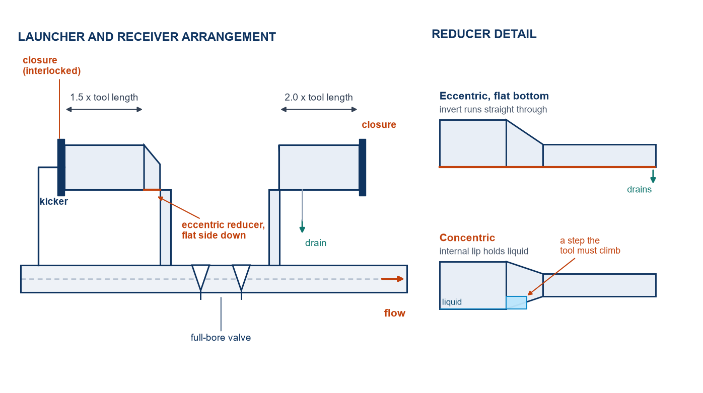
| Launcher barrel length | 1.5 × longest tool length, plus 1.2 m (4 ft) of working clearance | Enough to load the tool, close the door behind it and leave the sealing cups clear of the closure |
| Receiver barrel length | 2.0 × tool length, 2.5 × where debris is expected | The receiver has to hold the tool and what the tool pushed in front of it |
| Reducer | Eccentric, flat side down, one size step per reducer | Drains the barrel and gives the tool a continuous flat bottom to roll on |
| Kicker line | NPS 4 minimum, NPS 6 preferred on 16 in and above | Sized for the flow needed to start the tool, not for the throughput of the line |
Two of those rows are negotiable and two are not. Barrel bore and barrel length are set by the tool and can only be reduced by changing the inspection scope. The reducer type and the kicker size are engineering choices that a fabricator will happily make for you — which is exactly why they end up wrong.
Why the Reducer Sits Flat on the Bottom
A concentric reducer looks tidier on a drawing and is wrong in this service for two reasons. It creates an internal lip at the bottom of the bore, so condensate and water sit in the barrel instead of draining to the low point. And a multi-module tool arriving at that lip meets a step it has to climb, which is precisely the moment a cup can fold back or a joint can jackknife.
The eccentric reducer with the flat on the bottom keeps the invert continuous. Liquid runs out, the tool rolls in on a flat surface, and the weld seam sits where it can be inspected. The same logic applies at the receiver, where the arriving tool is usually wet and carrying debris: a flat bottom plus a drain at the lowest point is the difference between a trap that cleans out in an hour and one that needs a confined-space entry.
The Closure Is the Accident
Every fatal pig-trap incident has the same shape. A closure is opened while the barrel is still under pressure, the door or the pig leaves the barrel at speed, and the operator is in the line of fire. The mechanics are unforgiving: a 16 in closure door weighs tens of kilograms, and the stored energy behind it at 70 bar is equivalent to a small explosion.
The defence is mechanical, not procedural. A quick-opening closure must be fitted with a pressure-actuated locking device that physically prevents the door from being rotated or unlatched until internal pressure has been released. ASME BPVC Section VIII Division 1, UG-35(b) sets the requirement for quick-actuating closures, and the practical form of it is a bleed screw or vent valve interlocked with the latch: the operator cannot unlock the door without first opening a small vent, and if there is pressure behind it, the escaping gas tells them so while the latch is still engaged.
Three details decide whether that interlock survives contact with a real crew. The vent must discharge to a safe place, not at face height. The isolation valve upstream must be double block and bleed, so the barrel can be positively proved empty rather than assumed empty. And the closure must be rated for the full MAOP of the line, not for the pressure the station normally runs at — a trap designed at 40 bar on a 70 bar line is a trap that will be opened hot one day.
The Parts That Stop a Tool
A launcher is useless if the tool cannot get past the first valve. Four components cause most of the failures, and none of them is expensive to get right at the design stage.
- Reduced-bore valves. The trap isolation valve must be full bore, through-conduit. A standard gate valve with a reduced port is a mechanical stop for anything with cups on it.
- Unbarred tees. Any branch connection larger than about 2 in on a piggable line needs a barred tee, or the tool’s nose will try to enter the branch. The bars guide it across the opening without blocking flow.
- Bends tighter than the tool can negotiate. Three-dimensional radius is the industry norm for piggable lines; 1.5D tools exist and are common, but the operator has to confirm the specific tool. No code mandates 3D — NACE SP0102 gives guidance and the tool vendor gives the limit.
- Partially open check valves and unseated valves. A check valve that is not fully open, or a gate left half-travelled, presents an edge that a cup will catch on. The inspection programme assumes every valve is either fully open or fully closed.
Pressure Class, Wall and Material
The barrel is a pressure vessel built from pipe, and it is designed at a lower design factor than the mainline. Station piping sits in a Class 3 or Class 4 location, where 49 CFR 192.111 allows a design factor of 0.50 or 0.40 instead of the 0.72 available in Class 1. At the same MAOP that means a heavier wall than the line pipe it is welded to, and the transition usually happens at the first flange or at a shop weld inside the trap assembly.
For sour service the material rules change again. NACE MR0175/ISO 15156 applies to the barrel, the closure body, the reducer and every wetted component, with the usual consequence for carbon steel: hardness limited to 22 HRC and welds qualified accordingly. Where the line carries wet CO2 or chlorides, the barrel is often internally clad or solid corrosion-resistant alloy, and the closure is the part that decides the price.
| Service | Barrel | Closure and trim | Documentation to ask for |
|---|---|---|---|
| Sweet dry gas, Class 3 | API 5L X52 or better, impact tested | Carbon steel, 22 HRC max on trim | EN 10204 3.1, hydro test, UT of welds |
| Wet gas with CO2 | Carbon steel with corrosion allowance, or 3LPE internal lining | Duplex or 316 trim | 3.1 plus coating holiday test |
| Sour (H2S above NACE threshold) | Carbon steel to NACE MR0175 with PWHT, or clad | 22 HRC max, NACE qualified seals | 3.1, hardness survey, SSC test report |
| High-pressure transmission | Class 600 to 900 flanges, wall per B31.8 | Forged closure body, full MAOP rating | 3.1, PMI, NDE of closure body |
What Belongs on the Enquiry
A trap quotation is only as good as the data sheet behind it. Ten lines are enough to get a price that will not move, and each one corresponds to a decision that is expensive to change after fabrication.
- Line size, grade, wall and MAOP, with the class location at the trap.
- Longest tool length, tool OD and minimum bend radius, from the ILI vendor’s letter.
- Launch and receive orientation, and the available straight length upstream and downstream.
- Closure type: quick-opening, hinged or bolted blind, and whether an interlock is mandatory.
- Isolation valve type and bore, and whether it is in the trap scope or the station scope.
- Kicker and equaliser sizes, and the pressure source for each.
- Vent and drain destinations, including whether drains go to closed drain.
- Service: H2S and CO2 partial pressures, chlorides, temperature range.
- Test pressure and medium, and whether the client witnesses it.
- Documentation: 3.1 or 3.2, NACE, PMI, UT, coating, and the spool drawing set.
The steel in a trap is not the expensive part. The closure, the full-bore valve and the welding and testing behind them are, and all three are fixed by decisions made on the data sheet before a single plate is cut. A trap quoted from a line size alone will be either undersized for the tool or overpriced for the duty, and the difference only shows up on the day the first inspection run is scheduled.
Frequently Asked Questions
How long should a pig launcher barrel be?
Long enough to hold the longest tool plus working clearance behind the closure — in practice about 1.5 times the tool length plus 1.2 m (4 ft). A receiver is longer, about 2.0 times the tool length, because it also has to hold the debris the tool pushed ahead of it. Both numbers come from the tool, not from the pipe.
Can an inspection tool pass a 1.5D bend?
Often yes, but only for a specific tool. Bend radius capability varies by tool family and by diameter, and 3D is the conventional default for piggable lines because it keeps the tool vendor list open. There is no code number: NACE SP0102 gives guidance and the tool vendor gives the limit that applies to their equipment.
Does 192.150 apply to gathering lines?
No. Paragraph (b)(8) excludes gathering lines. That exemption is narrower than it used to be in practice, because more large-diameter gathering is now regulated under Part 192, but the ILI requirement itself is still written for transmission lines.
Does the trap need a higher pressure class than the line?
It needs at least the line’s MAOP, and its flanges must be rated for it at the design temperature. Many operators specify one class higher on the barrel and closure, because the trap sees the transients that the line does not — valve closure, slug arrival, and the pressure spike when a kicker is opened quickly.
Why is the reducer eccentric and not concentric?
Because a concentric reducer leaves a lip at the bottom of the bore. That lip traps liquid and gives an arriving tool a step to climb. The eccentric reducer with the flat on the bottom keeps the invert straight, drains the barrel and lets the tool roll in.
Is a pig signaller required?
Not by 192.150, which is about geometry rather than instrumentation. It is standard practice at both ends because the signaller is the only positive confirmation that the tool left the launcher and arrived at the receiver, and because the launch sequence and the receive sequence both depend on knowing where the tool is.
Related Reading
- Pig launcher and pig receiver — the fabricated assembly, its scope of supply and the data sheet we quote from
- Long-distance pipeline inspection: methods and QC process — what the tool measures once it is in the line
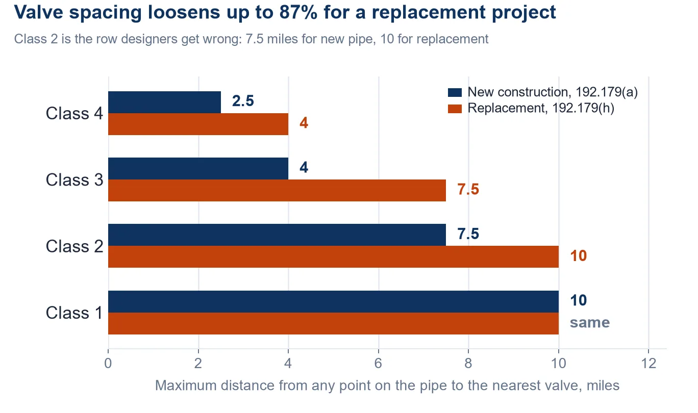
- Main line valve spacing under 49 CFR 192.179 — the valve spacing that decides how long a pig run can be
- Pipeline hydrotest pressure — the strength test that follows construction, and why it is not the mill test
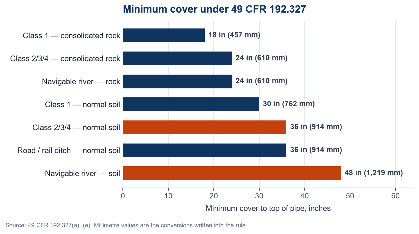
- How deep a gas pipeline must be buried — the cover table that sets the trench the trap sits beside
- API 5L line pipe grades, PSL1 and PSL2 — the pipe specification behind the barrel and the line