The short answer
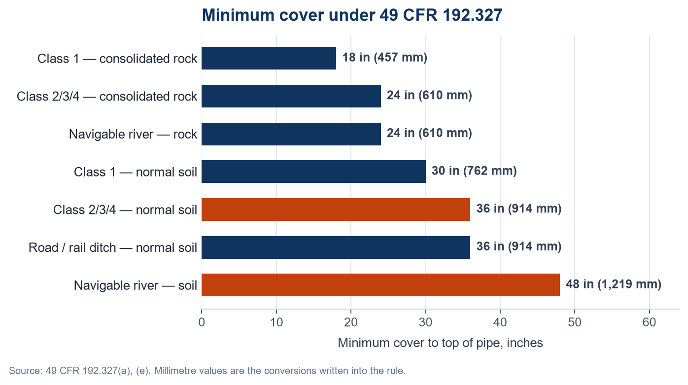
Under 49 CFR 192.327 a buried gas transmission line needs 30 in (762 mm) of cover in a Class 1 location and 36 in (914 mm) in Class 2, 3 or 4, measured from finished grade to the top of the pipe. In consolidated rock those figures drop to 18 in (457 mm) and 24 in (610 mm). Distribution mains need 24 in (610 mm). Across a navigable river the requirement is 48 in (1,219 mm) below the natural bottom. The number that decides which row of that table applies is not the pipe and not the pressure — it is the building count along the centreline.
Two sections of the same line, same diameter, same grade, same operating pressure, two kilometres apart on the same right-of-way. One is buried 30 in deep, the other 36. Nothing about the steel changed. What changed is how many houses stand within 220 yards of the centreline over a one-mile stretch, because that is the measurement the federal rule uses to decide how much earth must sit on top of the pipe.
Cover depth is the most frequently quoted and least frequently read part of pipeline regulation. Contractors know the 36-inch number, site crews know the 1-metre number, and both are right in some places and wrong in others. This page works through 192.327 as written: which table applies to which kind of line, what a class location actually is, where the rule permits less cover, and the one measurement convention that most as-built drawings get wrong.
The Cover Table, in Inches and Millimetres
Paragraph (a) of 192.327 sets cover for buried transmission lines. The values are minimums: a design may specify more, and many operators do, but nothing may specify less without one of the exceptions further down this page.
| Location | Normal soil | Consolidated rock |
|---|---|---|
| Class 1 location | 30 in (762 mm) | 18 in (457 mm) |
| Class 2, 3 and 4 locations | 36 in (914 mm) | 24 in (610 mm) |
| Drainage ditches of public roads and railroad crossings | 36 in (914 mm) | 24 in (610 mm) |
Three further numbers sit in other paragraphs of the same section and are routinely missed because they are not in the table. Buried mains — distribution, not transmission — need at least 24 in (610 mm), per paragraph (b). Pipe under a navigable river, stream or harbour needs 48 in (1,219 mm) in soil or 24 in (610 mm) in consolidated rock between the top of the pipe and the underwater natural bottom, per paragraph (e). Offshore pipe in water less than 12 ft (3.66 m) deep needs 36 in (914 mm) in soil or 18 in (457 mm) in rock; in water 12 ft or deeper the pipe must sit below the natural bottom unless it is held down by stanchions, anchors or heavy concrete coating, per paragraph (f).
The Number That Picks the Row: Class Location
A class location unit is an onshore strip 220 yards (200 m) on either side of the centreline, measured along any continuous one-mile (1.6 km) length of pipeline. Count the buildings intended for human occupancy inside that strip and the class falls out of the count. Each dwelling unit in a multi-unit building counts as a separate building, which is why an apartment block can move a segment up a class on its own.
| Class | Buildings in the class location unit | Design factor | Minimum cover |
|---|---|---|---|
| Class 1 | 10 or fewer | 0.72 | 30 in (762 mm) |
| Class 2 | More than 10, fewer than 46 | 0.60 | 36 in (914 mm) |
| Class 3 | 46 or more, or within 100 yd (91 m) of a place of public assembly occupied by 20 or more people on at least five days a week for ten weeks | 0.50 | 36 in (914 mm) |
| Class 4 | Buildings of four or more storeys are prevalent | 0.40 | 36 in (914 mm) |
The cover change from Class 1 to Class 2 is only six inches, and that is the smaller half of the story. The design factor in the last column falls from 0.72 to 0.60 at the same boundary, and again to 0.50 and 0.40. Design factor divides allowable hoop stress, so a class change does not just bury the pipe deeper — it usually thickens the wall as well, or lowers the operating pressure, or both. A route study that ignores class location until the pipe is ordered produces a line that has to be re-designed at the first housing estate.
Class location is also a record-keeping obligation, not an opinion. The operator has to hold documentation for the current class of every transmission segment and be able to show how it was determined. When new construction appears alongside a line, the class can change, and the cover that was compliant when the line was built can become a documented deficiency without anyone touching the pipe.
Cover Is Measured to Finished Grade, Not to the Trench Bottom
The dimension in the table runs from the finished ground surface to the top of the pipe — not the centreline, not the bottom of the trench, and not the top of the bedding. Three mistakes follow from that definition, and all three appear on real projects.
Surveying before the surface is finished. Cover is measured and recorded after backfill, then the road is reconstructed and 4 to 6 in (100 to 150 mm) of pavement and sub-base go on top. If the survey was taken to the old surface, the as-built now claims more cover than the pipe has. The error is invisible in the records and only shows up in a depth-of-cover survey years later, or in an excavation.
Measuring from the bottom of the excavation. On a rock trench with 6 in (150 mm) of sand bedding, the pipe top sits above the trench bottom. A crew measuring from the rock gets a number that is too large by the bedding thickness, which is exactly the margin a shallow section cannot afford.
Reducing cover without recording the protection. Where a slab or a casing is used to justify less cover — the exception described in the next section — the protection has to be designed and it has to be on the drawing. A shallow section with the slab value-engineered out is a shallow section with no legal basis, and it is also the section most likely to be hit by a mini-excavator.
When 36 Inches Will Not Fit
Paragraph (c) allows less cover where an underground structure — a sewer, a culvert, a foundation — prevents the required depth. The condition attached is not a formality: the line must be given additional protection to withstand anticipated external loads. The rule does not name the protection, which puts the burden on the designer to show what load is expected and what resists it.
In practice the protection is one of three things. A reinforced concrete slab or load-distributing plate spreads a wheel load over a wider area of soil. A steel casing or sleeve carries the load itself and keeps it off the carrier pipe. Deeper select backfill with a rock shield does the same job on rock. All three are engineered items with a wall thickness, a reinforcement schedule or a bearing capacity, and all three need to be in the pipe order at the same time as the line pipe — a casing procured after the line is laid is a casing that arrives late.
A casing is governed by its own three-part rule in 192.323. It must be designed to withstand the superimposed loads. Its ends must be sealed if water can get in. And if those ends are sealed without a vent, and the seal is strong enough to hold the maximum allowable operating pressure of the carrier pipe, then the casing itself must be designed to hold that pressure at a stress no higher than 72 percent of SMYS. That last clause is the reason casings are vented in most designs: a vent makes the annulus incapable of holding pressure, which both removes the 72 percent design case and turns the vent into a leak indicator at the surface.
Paragraph (d) is the other route to shallower cover, and it applies to mains rather than transmission lines. A main may go in with less than 24 in where state or municipal law sets a lower minimum, requires the main to share a trench with other utilities, and provides adequately for preventing damage from external forces. All three conditions, not one.
Rock, Rivers and Water
The rock column in the table is not a discount for difficult digging. Consolidated rock is competent enough to carry load across the pipe without transmitting it as a point load, which is why the cover can be reduced by a foot. The rock still has to be separated from the coating: a rock shield, sand padding or select backfill is required in every rock trench regardless of the cover figure, because the failure mode in rock is coating damage and subsequent corrosion, not crushing.
River crossings invert the logic. There, cover is not protecting the pipe from traffic above; it is protecting the pipe from the river. A scoured bed, an anchor drag or a dredger can expose a line that was buried to the drawing, which is why the requirement is written against the underwater natural bottom rather than the dredged or surveyed bottom, and why 48 in applies in soil where 24 in would be acceptable in rock. On a crossing where 48 in of cover cannot be achieved by open cut, the answer is a directional drill or a heavier-wall pipe designed for the installation loads — not a shallower trench.
What Cover Depth Costs in Steel
Cover requirements show up in the pipe order in four places, and each one has a different cost driver.
- Road and rail crossings. A cased crossing needs a casing pipe sized over the carrier, typically two nominal sizes up, with its own wall thickness and length, plus spacers, end seals and a vent. The casing is ordered with the line, not after it.
- Rock sections. The saving comes from bedding and shielding, not from upgrading the pipe. Buying a heavier wall to survive a rock trench is paying for the wrong solution.
- River crossings. Forty-eight inches of cover means a drill or a deep open cut, and the pipe is then designed for pull or flotation loads that have nothing to do with operating pressure. Wall thickness is set by the installation, and that is a separate calculation from the internal pressure design.
- Class transitions. Every change from Class 1 to Class 2 or 3 can change the design factor and therefore the wall. Getting the class boundaries right before the mill order is cheaper than a wall change after it.
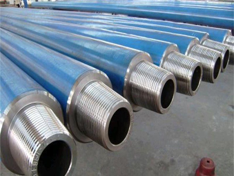
For the pipe itself, the relevant specifications are API 5L line pipe grades and the PSL1 versus PSL2 difference for the carrier, and 9-5/8 in casing for cased crossings where a standard casing size is specified. Both are ordered against wall thickness and drift, not against a nominal size alone.
How Cover Is Verified After Backfill
Because the dimension is to finished grade, the only meaningful check is a depth-of-cover survey taken after the surface is complete. That survey is the acceptance record: it is compared against 192.327 row by row, and any station that comes up short is a rework item, not a note. There is no paperwork route to compliance — cover cannot be reclassified, and a class location change makes the requirement stricter rather than looser.
The practical sequencing that avoids the problem is simple. Finish the surface, then survey. On a road crossing, that means the survey happens after the pavement, and the pipeline crew has to stay involved long enough to sign off a number that is set by another trade. Projects that hand the crossing over to the road contractor and close the pipeline file early are the ones that discover two inches of missing cover at the first integrity assessment.
Frequently Asked Questions
Does the 30 and 36 inch rule apply to a service line to a house?
No. 192.327(a) is written for buried transmission lines and 192.327(b) for mains. Service lines are governed by their own installation requirements and by state rules, and they are commonly shallower — which is one reason service lines are the most frequently struck part of a distribution system.
Are the millimetre values exact conversions?
They are the conversions written into the rule, rounded to the nearest millimetre: 30 in is 762.0 mm, 36 in is 914.4 mm and appears as 914, 24 in is 609.6 mm and appears as 610, 18 in is 457.2 mm and appears as 457, 48 in is 1,219.2 mm and appears as 1,219. Use the inch value as the governing figure and the millimetre value as its conversion, not the other way round.
Can cover be reduced with a concrete slab?
Yes, under 192.327(c), where an underground structure prevents the required cover and the line is given additional protection designed for the anticipated external loads. It is a design exception with a supporting calculation, not a blanket permission to bury shallow under a slab.
Is cover measured to the top or the centre of the pipe?
The top of the pipe. Charts and drawings that dimension to the centreline are showing a larger number than the rule asks for by half the outside diameter, which on a 24 in line is a full foot of apparent cover that does not exist.
Does a higher class location change the pipe grade?
Not the grade — the design factor. Class 1 allows 0.72 of SMYS in the hoop stress calculation, Class 2 allows 0.60, Class 3 allows 0.50 and Class 4 allows 0.40. For a fixed diameter and pressure that usually means a thicker wall, so the class boundary is a wall thickness decision as much as a burial decision.
Related Reading
- Natural gas pipeline spacing requirements — the horizontal clearances and separation distances that work together with cover depth
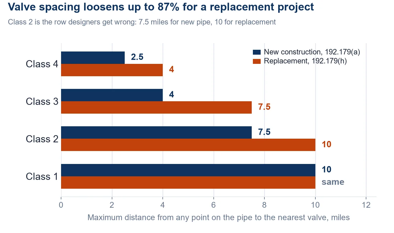
- Main line valve spacing under 49 CFR 192.179 — how far apart sectionalizing block valves must be, class by class, and the replacement table that relaxes it
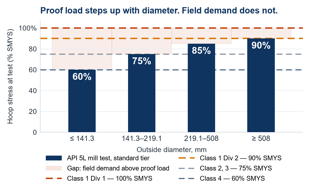
- Pipeline hydrotest pressure — why the mill test does not cover the field test, and how the strength test is set
- API 5L line pipe grades, PSL1 and PSL2 — the carrier pipe specification behind every buried section
- 9-5/8 in casing: weight, wall, ID and drift — the size most often specified as a crossing casing, with the dimensional table