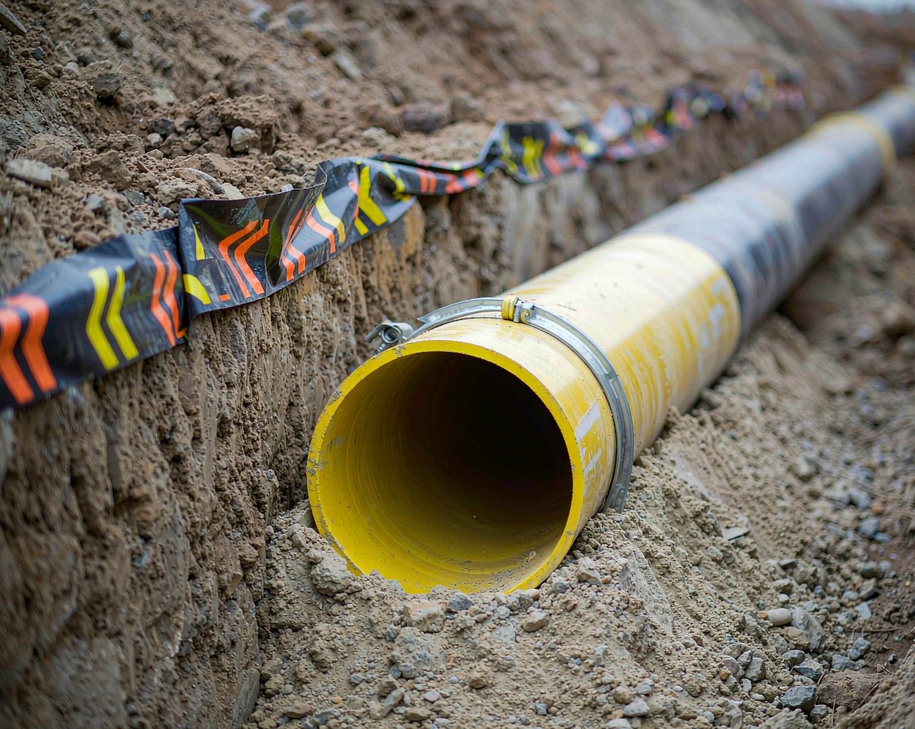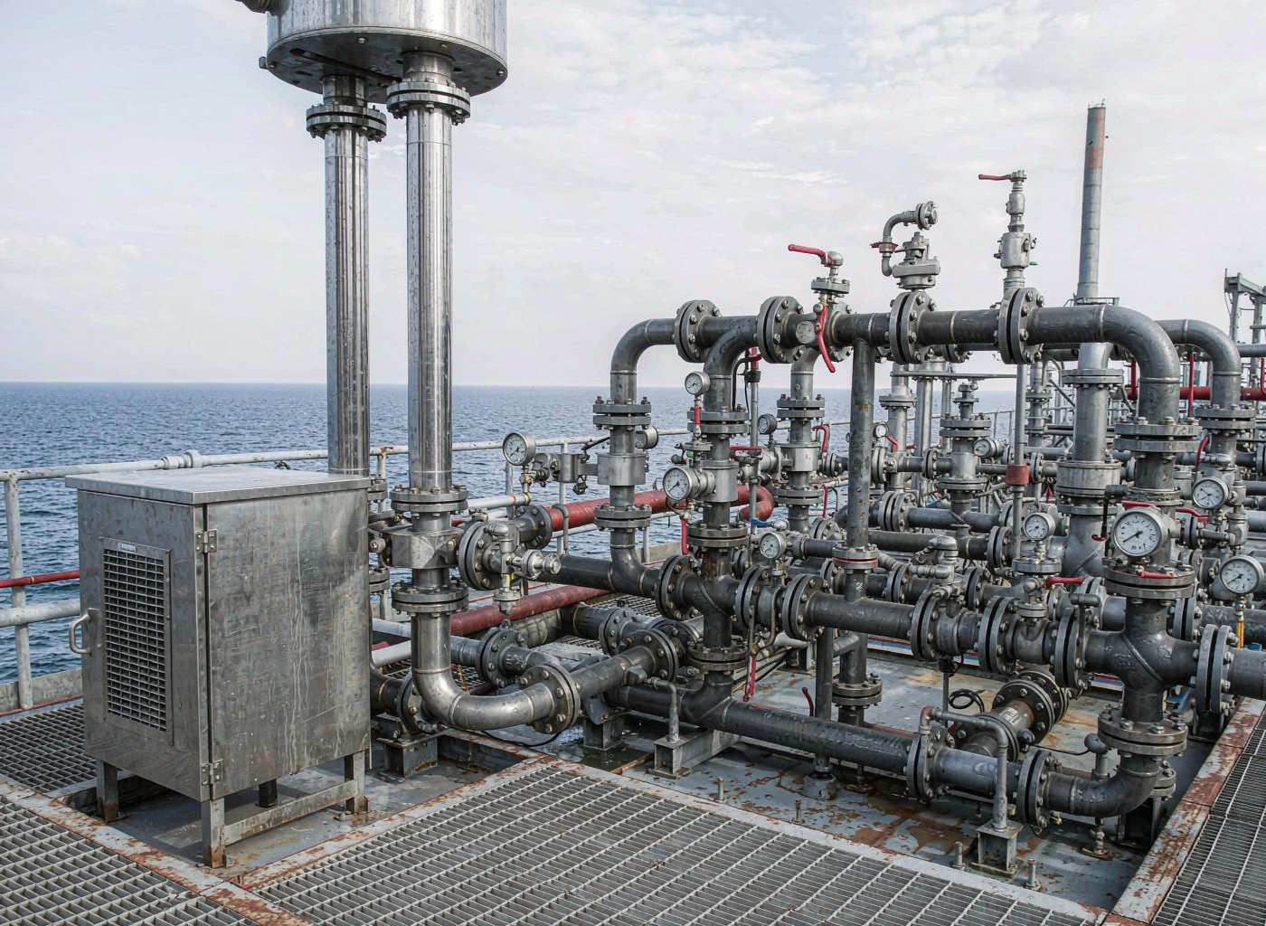
A long-distance pipeline cannot be shut down and opened up every time someone wants to know whether the wall is thinning. Inspection has to happen from the inside, from the outside, and — on subsea lines — from a vehicle working in zero visibility. This guide compares the inspection methods that are actually deployed on transmission pipelines, then walks through the sequence a quality inspection campaign follows from cleaning run to dig verification.
Key takeaways
- Two technologies carry most in-line inspection work: magnetic flux leakage (MFL) for metal loss and ultrasonic testing (UT) for wall thickness and crack sizing.
- Laser ultrasonic tools resolve stress corrosion crack depth through a probe area of about 0.5 mm — beyond conventional UT.
- External inspection splits by water depth: radiography and direct assessment onshore, divers to about 60 m, ROV-borne tools beyond that.
- Inspection is a process, not a tool: cleaning run, geometry run, ILI run, validation, dig list, excavation — skip a step and the dig list is guesswork.
What Pipeline Inspection Has to Catch
Three failure modes drive almost every inspection programme: metal loss from internal or external corrosion, cracking (stress corrosion cracking, fatigue, seam defects), and mechanical damage from third-party interference or ground movement. Each has a different detection physics, which is why no single tool covers a whole pipeline.
Subsea lines raise the stakes. International survey data puts internal corrosion behind more than half of subsea pipeline failures, and a subsea repair or section replacement costs an order of magnitude more than the onshore equivalent. Access is also the constraint: onshore crews can walk the route and adjust the inspection plan as they go, while a subsea line is inspected indirectly and repaired only with a vessel on station.
Internal Inspection Methods Compared
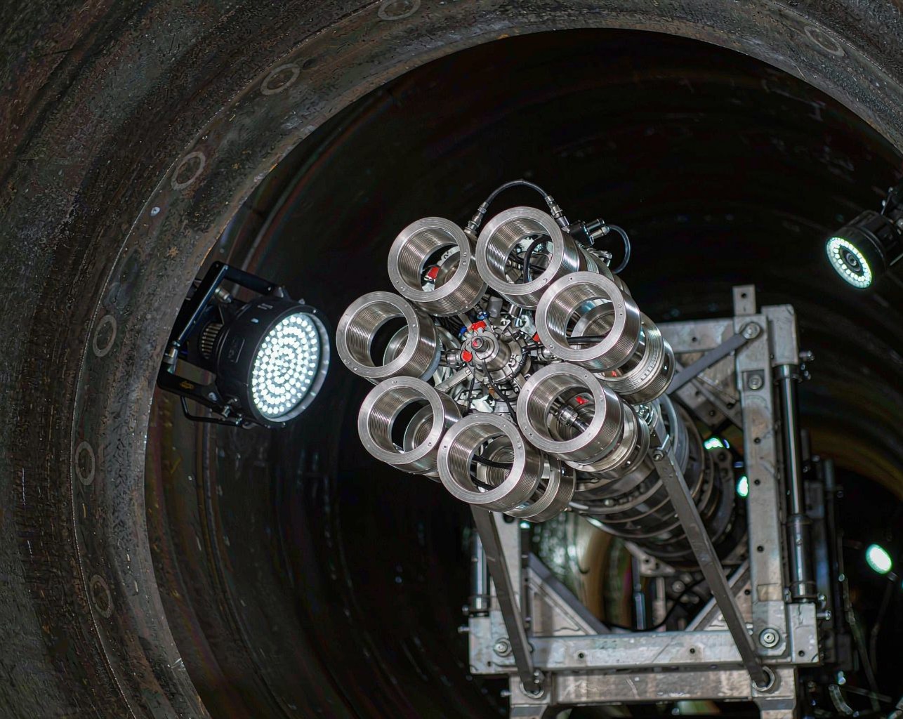
In-line inspection is unaffected by terrain, weather or water depth, which is why it is the backbone of integrity management on both onshore and subsea lines. The tools divide by detection principle.
| Method | Strength | Limitation | Best for |
|---|---|---|---|
| Magnetic flux leakage | High sensitivity to volumetric loss, fast, robust | Weak on tight, non-volumetric cracks | General corrosion, pitting, metal loss |
| Ultrasonic testing | Direct wall thickness, good crack sizing | Needs a liquid coupling medium | Wall thickness, crack depth, lamination |
| Electromagnetic acoustic (EMAT) | No couplant, works on gas lines | Limited penetration, lower resolution | Surface-breaking cracks |
| Inertial measurement | Maps route geometry and bending strain | No wall condition data | Ground movement, buckling, CP surveys |
| Laser scanning | 3D geometry and surface profiling | Complex, costly tooling | Dents, ovality, corrosion mapping |
Magnetic flux leakage
MFL magnetises the pipe wall; a defect distorts the field and leaks flux that sensor rings pick up. Resolution has improved steadily since Buckeye Pipeline combined residual-magnetic sensors with high-resolution MFL pigs in 2002, which for the first time allowed internal and external corrosion to be told apart from a single run.
Tool architecture still limits what can be seen. Most systems use axial magnetisers, which detect volumetric loss and general corrosion well but cannot discriminate specific axial features. ROSEN’s 762 mm and 914 mm tools use magnetic sensor segments with adjustable rings for consistent wall contact. TD Williamson’s spiral MFL tool evaluates the weld seam with a single magnetiser set and matches transverse high-resolution performance without lengthening the tool body, producing multiple data sets in one pass.
| MFL operating parameter | Typical specification | Practical meaning |
|---|---|---|
| Sampling frequency | 750 Hz | High-resolution defect geometry |
| Operating pressure | 2.1–13.78 MPa | Wide range, covers most transmission duty |
| Temperature range | −10 to 55 °C | Surface and shallow-water service |
| Running speed | Up to 2.53 m/s | Throughput without production loss |
Ultrasonic testing
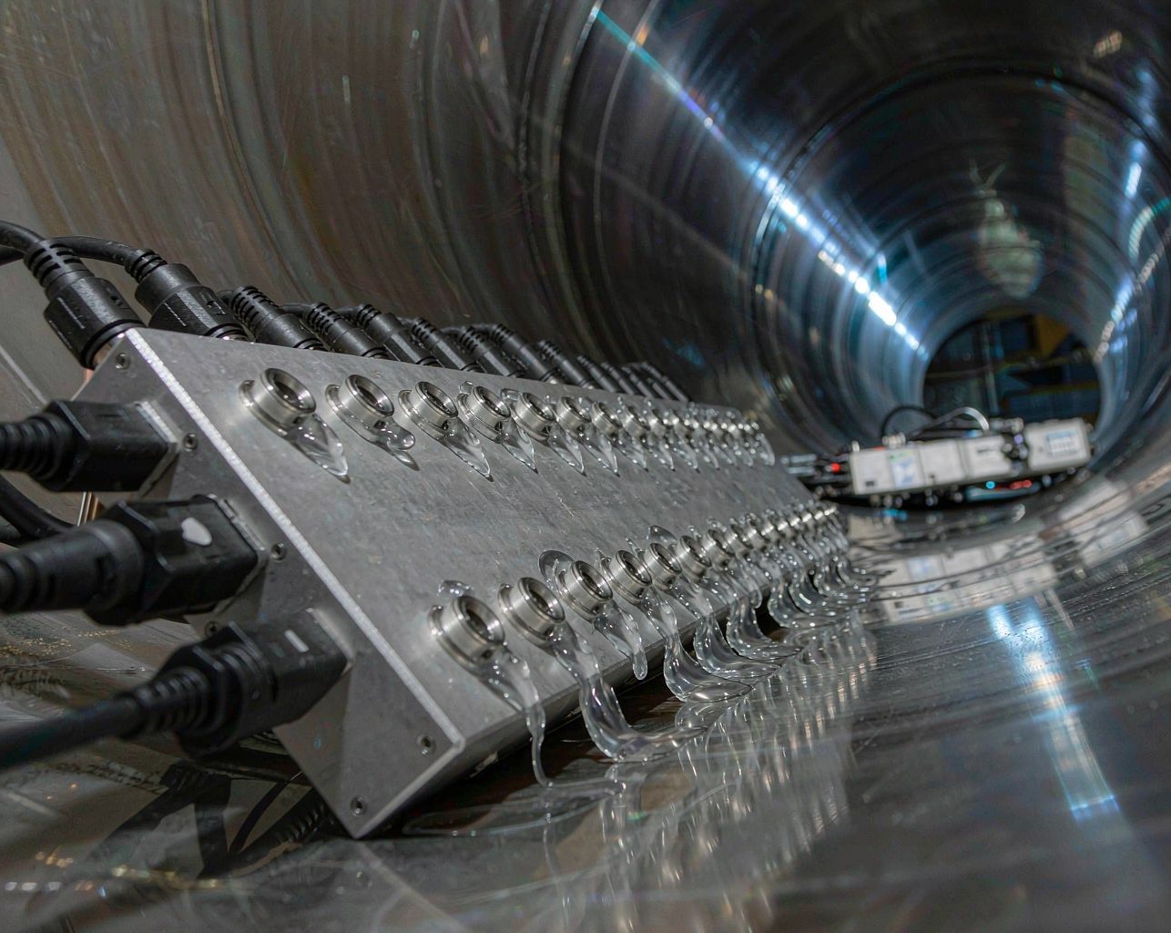
UT uses reflection, transmission and scattering to measure wall thickness, geometry and material change. Modern in-line UT began in the 1970s when Pipetronix ran ultrasonic scanning systems online; through the 1990s Nippon Steel built circumferentially arranged sensor arrays for wall-thickness logging, Shanghai University developed rotating-probe tools, and PetroChina followed with multi-probe automatic systems in the early 2000s.
Three generations now coexist. Conventional UT is contact-based and needs coupling, with moderate coverage. Array UT multiplies elements for better coverage and defect characterisation through signal processing. Laser ultrasonic generates ultrasound optically, giving a much broader frequency band and a probe area of roughly 0.5 mm, which is what makes it usable for stress corrosion crack depth rather than just wall loss. US Department of Transportation evaluations found laser UT with time-of-flight diffraction reliably measures SCC depth — the measurement that decides whether a crack is a dig-and-coat or a cut-out.
Combined tools
Because every method has a blind spot, combining two or more on one platform has become standard practice on high-consequence lines. ROSEN’s RoCorr-UT pairs MFL with UT: piezoelectric elements emit ultrasound that reflects off the internal and external walls, and transit times give defect length, depth and width at high precision — with MFL covering the areas the UT sensors miss. SmartPipe-style laser scanning tools add large-area corrosion mapping with 3D visualisation for the same reason.
External Inspection: Onshore, Shallow Water and Deep Water
External inspection splits cleanly by access. Buried onshore pipe is inspected radiographically at the weld during construction and by direct assessment afterwards; subsea pipe is inspected by whatever can reach it. Cover depth and separation from other services also govern how that buried section is protected and how easily it can be exposed for verification, and those metric limits are collected in natural gas pipeline spacing requirements.
| Method | Strength | Limitation | Application |
|---|---|---|---|
| Radiographic testing | High accuracy, permanent record | Radiation safety, limited mobility | Weld inspection during construction |
| Acoustic detection | Real-time, high sensitivity | Ambient noise interference | Leak location, subsea monitoring |
| Hydrocarbon sensing | Chemical specificity, early warning | Short range, sensor maintenance | Subsea leak confirmation |
| Fibre optic sensing | Distributed, continuous, real-time | Cost, installation fragility | Strain and temperature along the route |
Radiography
RT remains the most widely used construction-phase method for girth welds, run with crawlers carrying X-ray tubes or isotope sources before the trench is backfilled. Direct digital radiography — GE’s DXR250V being a common example — puts the image on screen immediately and removes film processing from the critical path.
Acoustic leak detection
Hydrophone-based detectors convert acoustic energy into electronic signals. Advanced units resolve leak rates down to 10 L/h with roughly 1 m positioning accuracy, which is enough to send a dive or ROV straight to the leak point. The CoLMar passive sonar system, with hydrophone arrays and pre-amplifiers, has been deployed on the 30 km Adriatic and 380 km Black Sea lines.
Hydrocarbon concentration sensing
A leaking subsea line disperses hydrocarbons into the water column. Subocean’s ROV-mounted SEASV sensor system samples hydrocarbon content in the seabed boundary layer and uses onboard logic to decide whether the signal originates from the pipeline, transmitting results over a dual communication link. The LongRanger variant reaches about 20 m for crude oil detection.
Distributed fibre optic sensing
Fibre bonded to the pipe strains with the steel, giving continuous spatial and temporal data at every point along the fibre — strain and temperature both. Optical time-domain reflectometry is the mature implementation; Brillouin-scattering OTDR is what Zhejiang University used in its serial subsea monitoring system for real-time long-distance coverage. The limitations are practical: fibre is fragile, splicing quality drives optical loss, and the installed cost is high relative to spot inspection.
How a Long-Distance Pipeline Quality Inspection Process Runs
This is the part that decides whether an inspection programme produces an actionable dig list or a stack of data. The sequence below is the standard one; compressing it is where most campaigns go wrong.
- Baseline review. Assemble design drawings, girth weld records, coating type, operating history, previous ILI reports and repair logs. The inspection plan is written against this, not against a generic template.
- Cleaning run. Wax, scale and debris degrade every downstream signal. A cleaning pig run — sometimes two — precedes the geometry and ILI runs, and the volume of debris recovered is itself an indicator of internal condition.
- Geometry and caliper run. Establishes bore, ovality, dents, buckling and any feature that could obstruct or damage the ILI tool. Skipping it is how tools get stuck.
- ILI run. MFL, UT or a combined tool, at a controlled speed and with the magnetic or coupling conditions the tool requires. Speed excursions are the most common cause of unusable data.
- Data validation and anomaly assessment. Signals are compared against the tool’s detection specification, then graded. In-line results are matched against known features — a previously recorded repair sleeve, a weld, a bend — to confirm the tool was correctly located and oriented.
- Dig list and excavation verification. Anomalies above the repair threshold are ranked by predicted failure pressure, not by depth alone. Excavation confirms the prediction; the confirmed result feeds back into the next assessment interval.
For pipeline operators, the practical consequence is that inspection findings translate directly into material decisions: a dig that reveals external corrosion under failed coating is a coating problem, while internal metal loss in the lower quadrant points to water accumulation and calls for either inhibitor management or a change of wall thickness on the next order.
Acceptance Criteria and Standards
Inspection results are only meaningful against a stated acceptance level. Most transmission pipeline ILI specifications are written to a detection and sizing tolerance agreed before the run — for example, 80% probability of detection for metal loss above 10% of wall thickness, with sizing accuracy quoted in percentage points at a confidence level. Without that statement in the specification, two contractors can report the same feature differently and both be technically correct.
The material side of the same question is covered by API 5L line pipe grades and PSL1 versus PSL2 requirements, and by the weld-quality discussion in AISI 4130 pipeline welding and the thermal envelope. Where the line carries wet or sour product, wall-loss rates and the corrosion allowances behind them are covered in pipeline external and internal corrosion protection and in cathodic protection technology.
Frequently Asked Questions
What is the difference between MFL and ultrasonic in-line inspection?
MFL magnetises the wall and detects the flux leaking from a defect, giving excellent coverage of volumetric metal loss quickly. UT measures wall thickness and crack depth directly using sound, which is more accurate for cracks but needs a liquid couplant and is slower.
How often should a long-distance pipeline be inspected?
The interval is set by the assessed corrosion rate and the remaining life of the highest-ranked anomaly, not by a fixed calendar. High-consequence lines commonly run every three to five years; lines with active corrosion or a history of cracking run more often.
Can a pipeline be inspected without stopping the flow?
Yes. ILI tools travel with the product, so the line keeps operating. The practical constraint is speed and pressure stability during the run rather than throughput — most tools operate up to about 2.5 m/s within a 2.1–13.78 MPa window.
How deep can subsea pipelines be inspected?
Divers work to roughly 60 m. Beyond that, ROVs carry the inspection payload — acoustic leak detectors, hydrocarbon sensors or ultrasonic arrays — and are controlled from the surface vessel.
What causes an ILI run to produce unusable data?
Speed excursions, inadequate cleaning, low product pressure for the tool’s specification, or a geometry feature that stopped the tool short. All four are preventable at the planning stage, which is why the cleaning and caliper runs are not optional.
Wall thickness is a purchasing decision. SHUNFU METAL supplies API 5L line pipe, API 5CT casing and CRA pipe in 13Cr, Super 13Cr, duplex and nickel alloys, with wall thickness, impact testing and MTR traceability matched to the inspection specification. Tell us the line size, grade and service condition and we will quote against it. Request a quotation.