By Harris, Technical Staff, SHUNFU METAL
Laser quenching is a two-dial process: laser power and scanning speed. Spot size and track overlap are geometry; everything that matters for hardness and wear sits on those two dials. This article decodes the nine-run process window published for 4145H drill collar steel by Li Yingjie et al. in Heat Treatment of Metals (2019, 44(8):169–175) and argues a point that most process brochures hide: scanning speed, not power, is the variable that decides whether you get fine martensite, coarse martensite, or nothing at all.
4145H and Its Steel-Grade Neighbours
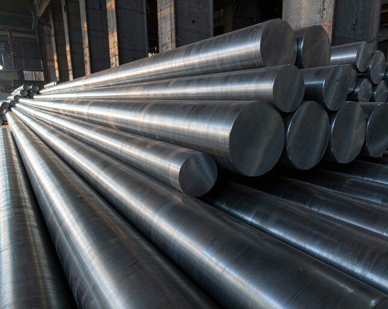
4145H is the AISI chromium-molybdenum H-steel of the oilfield, registered as UNS G41450 and supplied to ASTM A29/A304; the H suffix guarantees a hardenability band under A304, which is why it is the designated material for drill collars and heavy-weight drill pipe in API Specification 7-1. In China the grade is produced for the petroleum drill-collar standard SY/T 5144, and buyers routinely ask for the domestic GB/T 3077 substitute 42CrMo. The nearest EN counterpart is 42CrMo4 (W.Nr. 1.7225), and the same family appears as JIS SCM440 in Japan — with an important caveat: 42CrMo4 carries less carbon (0.38–0.45% versus 0.42–0.49%), so it hardens on a slightly different window. The 2019 study used a drill-collar-tightened 4145H whose nominal chemistry is C 0.43–0.47, Si 0.20–0.30, Mn 1.00–1.10, P ≤0.020, S ≤0.020, Cr 1.10–1.20, Mo 0.20–0.25 (mass %).
The Two Dials and the Energy Budget
The physics is an energy budget. Heat input per unit area scales with laser power and shrinks as the beam moves faster, so speed and power trade against each other one-to-one: doubling the speed halves the energy delivered to every point, and raising the power merely buys it back. Typical industrial data published online for 42CrMo4 shafts sit at 1–10 kW, 5–15 mm/s scan speed, 6–20 mm spot, 0.3–2.0 mm hardened depth and 55–62 HRC surface. The 4145H study sits inside that window, but at its low-power, low-speed corner: 1.5–2.0 kW, 400–800 mm/min (6.7–13.3 mm/s), and a φ10 mm spot. That placement is the first warning: this grade needs the slow end of the window.
| Parameter | Typical industrial (42CrMo4 shafts) | 4145H study matrix |
|---|---|---|
| Laser power | 1–10 kW (often 2–4 kW) | 1.5 / 1.8 / 2.0 kW |
| Scan speed | 5–15 mm/s (300–900 mm/min) | 400 / 600 / 800 mm/min |
| Spot size | 6–20 mm | φ10 mm |
| Hardened depth | 0.3–2.0 mm | Surface layer, fine martensite |
| Surface hardness | 55–62 HRC | 23.6–55.7 HRC across the matrix |
Speed Decides the Microstructure: Martensite, or Nothing
At 400 mm/min the surface absorbs enough energy to cross the austenitizing temperature, and the cold base then self-quenches it into fine acicular and lath martensite. Raise the speed to 600 mm/min and the martensite turns visibly coarse: heating and cooling run faster, transformation temperatures shift, and the austenite has less time to homogenize. Push to 800 mm/min and the energy per unit area falls below the transformation threshold altogether — no martensite appears, the pearlite-dominated base structure survives, and the “quench” never happens. In other words, the structure flips from fine martensite to coarse martensite to no martensite simply by changing how fast the beam moves.
Power gets the attention; speed is the boss. A 1.5 kW beam at 400 mm/min hardens better than a 2.0 kW beam at 800 mm/min. Every kilowatt you add can be undone by a few hundred mm/min of extra speed, and at 800 mm/min with a 10 mm spot on 4145H the laser is effectively switched off — you paid for a kilowatt and got nothing.
Hardness: Three Windows That Tell the Whole Story
Hardness was measured on the HRC scale at three points per specimen — first-track centre, second-track centre and track-overlap centre — with 150 kg load and 6 s dwell. Grouped by scan speed, the nine specimens fall into three sharply separated windows:
| Specimens | Scan speed (mm/min) | Hardness range (HRC) | Spread | Microstructure |
|---|---|---|---|---|
| 1, 4, 7 | 400 | 42–57 | Δ15 | Fine acicular + lath martensite |
| 2, 5, 8 | 600 | 32–52 | Δ20 | Coarse martensite |
| 3, 6, 9 | 800 | 27–39 | Δ12 | Pearlite retained, no hardening |
Within each speed group, power lifts hardness: the 1.5 kW samples sit at the bottom of the window, the 2.0 kW samples at the top, and the maximum of the entire matrix — 55.7 HRC — belongs to specimen 7 at 2 kW and 400 mm/min. The paper also records two production-relevant details. Hardness at the second track is consistently higher than at the first, because residual heat from the first pass raises the base temperature and improves laser absorptivity, so more energy enters the steel. The overlap centre dips instead, because the second track re-heats the first and causes local self-tempering. The measured first-track decline is stark: at 1.5 kW the first-track centre reads 42.3 HRC at 400 mm/min, 32.9 HRC at 600 mm/min and 23.6 HRC at 800 mm/min — a collapse of nearly 19 points purely from speed.
Wear Modes Flip as Speed Rises
Dry ball-on-disk tests (4 mm ball, 100 N, 200 r/min, 30 min) completed the picture, and the wear mechanism changes with the same dial. At 400 mm/min the surface shows ploughing and scratching grooves with no spall pits — mild, stable wear. At 600 mm/min cracks appear, the friction layer fragments and delaminates, and the dominant mechanism becomes spalling. At 800 mm/min the damage is severe: heavy adhesion and oxidation wear, large amounts of frictional heat, and oxide scale bonded to the worn surface. Wear loss follows the same logic as hardness — it grows as speed rises and shrinks as power rises — and the minimum of the whole matrix sits at 400 mm/min with 2 kW.
| Scan speed (mm/min) | Dominant wear mode | Surface condition |
|---|---|---|
| 400 | Ploughing / scratching | Light, no spall pits |
| 600 | Spalling / delamination | Cracks, flaked friction layer |
| 800 | Adhesive + oxidative | Severe, oxide scale, high friction heat |
The mechanism chain is the story worth remembering: fine martensite raises hardness, higher hardness resists plastic deformation, less deformation means the counter-body ball digs in less deeply, the real contact area shrinks, and wear drops. The paper adds a caution that should worry every process owner: across specimens 3, 6 and 9 the power kept rising, yet the wear damage did not improve correspondingly — the higher speed quietly cancelled the power benefit. Speed is the boss here too.
Practical Rules for Process Owners
- For 4145H with a φ10 mm spot, keep scan speed at 400 mm/min or below and use at least 2 kW; expect 42–57 HRC on the hardened zone and a 55.7 HRC peak at the best setting.
- Design track spacing around the overlap dip — the second pass self-tempers the first, so an improvised overlap creates a soft stripe that becomes the future wear line.
- Do not copy parameters across grades and beam sizes: published 42CrMo4 results (e.g. 1200 W, 20 mm/s, 6 mm spot, ~0.97 mm case) work because of a different energy density; the same recipe on 4145H at a 10 mm spot is off-window.
- Verify every batch with a hardness profile and metallography, and request the wear test data — the window, not the marketing peak, is what you are buying.
The Bottom Line
For 4145H drill tools, scanning speed is the dominant variable and the proven sweet spot is 400 mm/min with 2 kW: fine martensite, 55.7 HRC, minimum wear loss and mild ploughing-type damage. Generic process sheets that advertise a single “58–62 HRC” number hide the real geometry of this problem — a narrow, speed-limited window in which too much speed does not just soften the case, it switches the laser off. SHUNFU METAL supplies 4145H drill-collar stock and validates laser-quench windows against published data before any production run, because on a drill string, the window is everything.