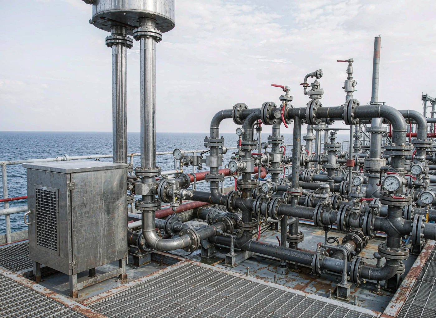
17-4PH is a martensitic precipitation-hardening stainless steel. It combines corrosion resistance approaching that of austenitic stainless steels with the ability of martensitic grades to be strengthened by heat treatment — a combination of corrosion resistance and high structural strength that has kept the grade in wide use across chemical processing and pulp and paper equipment, as well as aerospace, marine and nuclear applications. It also costs less than ordinary austenitic stainless steels.
The grade contains approximately 17% chromium and 4% nickel, plus about 4% copper and 0.3% niobium — “17-4” refers to the approximate chromium and nickel contents, and “PH” stands for precipitation hardening. The Chinese designation for the grade is 05Cr17Ni4Cu4Nb; the US cast grade designation is CB7Cu-1, with UNS number S17400, commonly known as type 630.
With its low carbon content, medium nickel content and a fine lath martensitic structure that develops good toughness after aging, 17-4PH would be expected to cut and weld well in the hot-working condition. In actual production, however, the steel proved prone to cracking when it was plasma cut or welded. This article follows a production case — centrifugally cast 17-4PH tubes for a screen basket frame in a pulp screening installation, with finished dimensions of Ø1100 mm × 60 mm × 800 mm — and analyzes why cracks formed during hot cutting and welding, and which process changes finally eliminated them.
Chemical Composition of 17-4PH Stainless Steel
17-4PH is a low-carbon, high-chromium, medium-nickel, high-copper high-alloy steel. GB/T 20878-2007 (Stainless and heat-resisting steels — Designation and chemical composition) specifies the chemistry of grade 05Cr17Ni4Cu4Nb. Table 1 shows the chemical composition of the pipe fittings that cracked, compared with the GB/T 20878-2007 limits. Every element is within specification — the cracking was a processing problem, not a material problem.
| Element | C | Si | Mn | P | S | Cr | Ni | Cu | Nb | Mo | V |
|---|---|---|---|---|---|---|---|---|---|---|---|
| Actual | 0.05 | 0.59 | 0.66 | 0.033 | 0.008 | 16.33 | 3.85 | 3.06 | 0.28 | 0.11 | 0.06 |
| GB/T 20878-2007 | ≤0.07 | ≤1.00 | ≤1.00 | ≤0.040 | ≤0.030 | 15.50–17.50 | 3.00–5.00 | 3.00–5.00 | 0.15–0.45 | — | — |
Table 1: Chemical composition of the 17-4PH stainless steel pipe fittings (wt%), compared with the GB/T 20878-2007 specification for grade 05Cr17Ni4Cu4Nb.
Weldability of 17-4PH Stainless Steel
Because of its low carbon content, 17-4PH is generally considered to have good cuttability and weldability. The grade normally requires neither preheating nor post-weld heat treatment. Where weld toughness is the priority, austenitic stainless steel consumables can be used — with the caveat that, since austenitic weld metal does not respond to aging, such joints are not strength-matched to the base metal. To obtain a strength-matched joint, consumables matching the base metal composition should be used, followed by the same low-temperature aging treatment applied to the base metal. In multi-pass welding, the individual passes and heat-affected zones end up with different properties; solution treatment is required to eliminate the differences, followed by aging to reach matching strength.
In actual production, however, this grade proved highly prone to hot-cutting cracks and welding cracks when processed by high-energy-rate methods — plasma cutting, and manual or semi-automatic arc welding. Good general practice for the wider family is covered in our guide to welding stainless steel; the sections below deal with what is specific to 17-4PH.
Effect of Alloying Elements on Weldability
The hot-cutting and welding crack susceptibility of a metal depends closely on which alloying elements it contains and in what amounts. The “carbon equivalent” concept widely used in engineering for rating weldability was developed for carbon steels and low-alloy steels, and it is not applicable to the highly alloyed 17-4PH. For this grade, weldability must be judged primarily from practice.
17-4PH contains seven common alloying elements — C, Cr, Ni, Cu, Nb, Si and Mn. Si and Mn are not primary additions and are present at low levels, so their influence on weldability is minor. The main elements affect weldability as follows.
Carbon (C)
Carbon strongly affects both the heat-treatment response of the steel and the properties of the weld metal, including toughness. Carbon determines the solidification morphology of the weld metal: keeping carbon low (≤0.07%) suppresses the peritectic reaction, makes planar and cellular crystal growth more likely, and reduces sulfur segregation — all of which improve toughness. Carbon also markedly increases hardenability, raising the hardness and strength of the weld metal at the expense of ductility.
Chromium (Cr)
Chromium is the principal alloying addition for corrosion resistance. In welding terms, however, chromium shifts the isothermal transformation (C-curve) to the right, increasing hardenability and hardening capacity and raising the brittle transition temperature — all adverse to weldability.
Nickel (Ni)
Nickel is an austenite (γ) former and increases hardenability. When the nickel content of the weld metal is high, the structure after welding can be martensitic, reducing toughness; martensite-austenite (M-A) constituents also form readily, making the weld more brittle.
Copper (Cu)
Copper is the element that drives age hardening in 17-4PH. Copper dissolves in the matrix during solution treatment or weld pool formation, and the martensite obtained after rapid cooling is strongly supersaturated in copper. A high copper content promotes grain-boundary segregation and blocky segregation during welding, lowering ductility and toughness and making weld cracking more likely.
Niobium (Nb)
Niobium is a strong carbide former. Its effect on weld toughness works mainly through changes in the weld microstructure: Nb reduces grain-boundary ferrite but increases side-plate ferrite and acicular ferrite, which raises hardness. Because of its strong affinity for carbon, Nb can also form hard, brittle carbides. If the weld is heat treated after welding, niobium precipitation hardening further reduces toughness.
Case Study: Cracking in the Original Production Route
The Original Process Route
At order placement, the customer specified the following production route: steel melting → centrifugal casting → homogenizing heat treatment → cutting-off → rough machining of end faces and inner/outer surfaces → solution treatment → flange welding → aging → microstructural and mechanical property testing → finish machining of inner/outer surfaces → non-destructive examination and subsequent operations.
The part — a screen basket frame for a screening unit in a pulp and paper plant — required mainly high corrosion resistance with modestly elevated mechanical properties. To control cost, the customer did not want the more conservative sequence of rough machining → solution + aging → flange welding → a second solution + aging, and chose the route above. The customer had not carried out a welding procedure qualification for the grade in the solution-treated condition.
During order review, the supplier warned that welding the flange after solution treatment, without aging first, would likely produce weld cracks. The customer’s position could not be changed, so the two sides agreed that the supplier would deliver the parts in the solution-treated condition, and the customer would perform the flange welding and the aging treatment themselves. Once production began under this route, cracks appeared in succession at the cutting-off (hot cutting) stage and at the flange welding stage.
Plasma Cutting Cracks
After homogenizing, the tube wall was far too thick (about 80 mm) to be cut off by lathe tool alone: the tool could reach a depth of 40 mm from the outer surface with a kerf 6 mm wide, leaving roughly 35–40 mm of wall uncut. Plasma cutting was therefore used to sever the remaining sections, after which the end faces were machined flat. In this way the tube was divided into three sections — head, middle and tail.
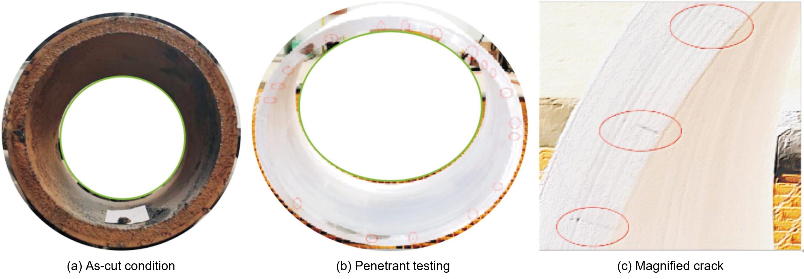
After the end faces were machined, multiple cracks were found in the tube wall. Dozens of fine cracks radiated from the tube axis outward along the radius toward the outer wall, distributed evenly around the circumference and evenly spaced. Viewed closely, the cracks opened from the inner wall outward and were 15–40 mm long; most did not run through the full wall thickness. On the inner surface, the cracks extended 2–7 mm in the axial direction. Of the three cut sections, one showed cracks at both ends, while the other two showed cracking at one end only. The crack positions corresponded exactly to the thickness and location of the plasma cut. The distribution and morphology of the cracks are shown in Figure 1. The defect was beyond recovery — the parts were scrapped.
Flange Welding Cracks
In the replacement batch, a preheating step was added ahead of plasma cutting, the sections were cut without any cutting cracks, and the parts moved through the remaining operations. They were solution treated and shipped to the customer. Not long afterwards, the customer reported that penetrant testing of the completed flange welds had revealed dozens of cracks on the inner and outer surfaces of the welded area. The customer suspected a material quality problem; testing, however, showed that the chemical composition met GB/T 20878-2007 (Table 1) — the material was sound.
A visit to the customer’s site established the welding conditions: a solution-treated 17-4PH flange had been welded to a solution-treated 17-4PH base tube, using matching consumables (ER630 filler wire), TIG (argon-arc) welding for the root pass and semi-automatic gas-shielded welding with argon backing, with a Y-groove whose root depth was 2 mm. This was the customer’s first job with the grade, and no welding procedure qualification had been performed for 17-4PH in the solution-treated condition before welding began. The welding parameters used are listed in Table 2.
| Parameter | Value |
|---|---|
| Filler wire | ER630 |
| Filler wire diameter | 2.0 mm |
| Welding position | Flat |
| Preheating | Not required |
| Post-weld heat treatment | Not required |
| Interpass temperature | — |
| Post-heating | As required |
| Current type and polarity | 110–140 A, DC, straight polarity (electrode negative) |
| Travel speed | 120–200 mm/min |
| Tungsten electrode type | Ceriated tungsten |
| Tungsten electrode diameter | Ø2.0 mm |
| Nozzle bore diameter | Ø10 mm |
| Shielding gas (argon) flow rate | 10–15 L/min |
Table 2: Argon-arc (TIG) welding parameters used for the 17-4PH stainless steel pipe fitting — TIG root pass with argon backing and semi-automatic gas-shielded welding.
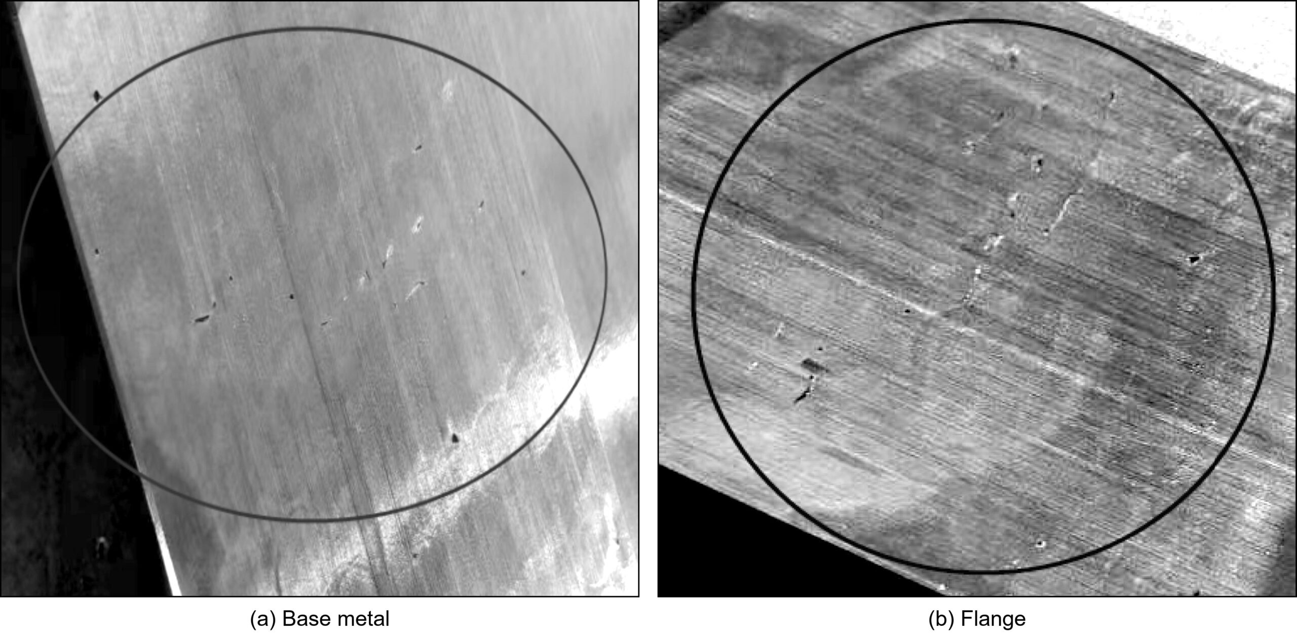
To investigate the cause, the welded flange of one part was machined down to reveal the cracks, and on another part the flange was removed completely, to expose defects in the base metal. Cracks visible to the naked eye were found in both the base metal and the flange, similar in form (Figure 2). The welding cracks occurred mainly within the V-groove, mostly at mid-wall thickness, with some pit-like porosity judged to be weld gas pores.
Root Cause Analysis
Plasma Cutting Cracks: Martensite Formed and Quenched by the Cutting Process
The cuts were made by high-energy-rate plasma cutting. In this process the energy density of the arc is very high and the plasma jet is relatively wide, so the cutting speed is fast: the metal melts rapidly and then solidifies rapidly. The resolidified cut metal and the heat-affected zone at its edges form a brittle, crack-prone high-alloy martensite. Under these rapid heating and rapid cooling conditions, the martensite develops cold cracks — which then propagate into the heat-affected zone.
Welding Cracks: Poor Ductility and High Internal Stress in the Solution-Treated Condition
Welding resembles high-energy-rate cutting in that both are high-energy-rate hot processes. The welding cracks traced back mainly to the condition of the material: the parts were welded in the solution-treated state, where ductility is very poor and internal stress after solution treatment is high.
Table 3 gives the mechanical properties of the pipe fitting after solution treatment (1040°C / 170 min, water quench) and after aging at 520°C and 620°C for 350 min. The data show clearly that in the solution-treated condition, tensile strength Rm, yield strength Rp0.2, elongation after fracture A and reduction of area Z are all far lower than after aging: elongation is only 2.5–3.5% and reduction of area only 6–7%, against 14.0–18.5% and 38–50% after aging. Aging precipitates copper-rich particles — precipitation hardening — which raises strength and hardness (peak values of Rm 1213–1225 MPa and 388–391 HBW after aging at 520°C). At the same time, the lath martensite obtained by solution quenching is itself aged: it converts into a very fine acicular (“hidden needle”) martensite, which markedly improves ductility. This is the special heat-treatment principle of 17-4PH precipitation-hardening stainless steel. (Solution temperature plays a similarly decisive role in other precipitation-hardening grades — see our study of solution treatment temperature effects in 15-5PH stainless steel.)
| Solution treatment (water quench) | Aging (air cool) | Rm / MPa | Rp0.2 / MPa | A / % | Z / % | Hardness / HBW |
|---|---|---|---|---|---|---|
| 1040°C / 170 min | None | 1023 / 1011 / 1016 | 892 / 888 / 885 | 2.5 / 3.5 / 2.5 | 7 / 6 / 6 | 320 / 316 / 318 |
| 1040°C / 170 min | 520°C / 350 min | 1213 / 1218 / 1225 | 1120 / 1118 / 1126 | 14.0 / 14.5 / 13.0 | 38 / 40 / 35 | 388 / 389 / 391 |
| 1040°C / 170 min | 620°C / 350 min | 1005 / 991 / 998 | 876 / 866 / 861 | 15.0 / 18.5 / 15.5 | 46 / 50 / 48 | 335 / 327 / 329 |
Table 3: Mechanical properties of the 17-4PH pipe fitting after solution treatment and after aging. Values are given as results for test specimens 1 / 2 / 3. Rm — tensile strength; Rp0.2 — 0.2% proof strength; A — elongation after fracture; Z — reduction of area.
Welding 17-4PH in the solution-treated condition therefore combines two adverse factors: (i) a martensitic structure with very poor ductility — the main contributor to weld cracking; and (ii) quench martensite with high internal stress in both the base tube and the flange, where rapid heating during welding releases that stress and produces heating cracks. In the welding thermal cycle, the fusion zone and heat-affected zone of the low-ductility, solution-treated base metal and flange experience a rapid thermal cycle with severe thermal expansion and contraction; when the stress exceeds the tensile strength of the material, thermal cracks form in both the base metal and the flange.
How the Cracks Were Eliminated
Preheating Before Plasma Cutting (450–600°C)
The reasoning behind the cutting fix: if the molten metal produced by cutting can cool slowly, or if the martensite that forms can self-temper, the martensite softens and cutting cold cracks are avoided. The cutting procedure was therefore changed: after homogenizing and cooling, about 40 mm of the wall was first turned off on the lathe; the section was then heated to 450–600°C and plasma cut. Because the wall is thick, natural cooling is slow — so the plasma-cut zone ended up as mostly pearlite with only a little martensite, and the small amount of martensite that formed was self-tempered. Rough machining and penetrant inspection of the cut faces showed no cracks, and the problem was solved. The drawback of this method is that working conditions are relatively poor (handling and cutting hot workpieces).
Welding in the Solution-Treated and Aged Condition
The welding cracks traced back mainly to the solution-treated state: poor ductility and high internal stress. A part welded in the solution-treated + aged condition instead starts welding from a ductile, fine acicular martensitic structure with low internal stress — a far better starting point for the welding thermal cycle. With the revised route, and using the welding parameters in Table 2, penetrant and radiographic testing of the weld, base metal and flange found no cracks.
The Revised Process Route
Based on the analysis of the process route and the crack causes, the sequence was redesigned. The original route placed solution treatment before flange welding; the revised route gives the parts a full solution + aging treatment before welding, so both base metal and flange enter welding in the tough, low-stress condition, and then repeats solution + aging after welding:
steel melting → centrifugal casting → homogenizing treatment → turning off part of the wall thickness, heating, plasma cutting → rough machining of end faces and inner/outer surfaces → solution treatment + aging → flange welding → solution treatment + aging → acceptance of test pieces → finish machining → non-destructive examination and subsequent operations.
With this route in production, the plasma cutting stage no longer produced cutting cracks. Parts welded with the parameters of Table 2 passed penetrant and radiographic inspection of the weld, base metal and flange — no cracks were found.
Conclusions
- Plasma cutting cracks were caused by martensite formed during cutting and cracking on rapid cooling — cold cracks. Preheating the pipe to 450–600°C before plasma cutting prevents this type of cracking.
- When 17-4PH stainless steel is welded in the solution-treated condition, the very poor ductility of solution-quenched martensite and the high internal stress lead to welding thermal cracks under the rapid heating and cooling of welding. For good weldability, 17-4PH should be welded in the solution-treated and aged condition.
- By revising the production route and the process controls — including preheating before plasma cutting — cold cracks from cutting were avoided, and welding in the solution + aged condition provided a favorable initial microstructure and low internal stress, avoiding welding thermal cracks.
Adapted from Wang Rongcheng and Hu Shunzhong, “Analysis of Cracking Occurring in Hot Cutting and Welding Processing of 17-4PH Stainless Steel Pipe Fitting,” Steel Pipe, Vol. 53, No. 4, 2024, pp. 66–70 (DOI: 10.19938/j.steelpipe.1001-2311.2024.4.66.70). Shunfu Metal is an API Q1 certified manufacturer of stainless steel and nickel alloy pipe, tubing and pipe fittings for oil and gas, chemical and process industry service.