“4130X” Is a Chinese Hydrogen-Service Variant of a Five-Standard Cr-Mo Family
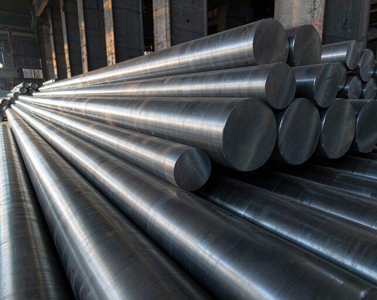
The steel in the source paper is 4130X, a Chinese Cr-Mo grade developed for large-volume seamless high-pressure hydrogen storage vessels. The material standard is GB/T 33145—2016 (large-volume steel seamless gas cylinders), the performance callout is T/CATSI 05003—2020 (special technical requirements for hydrogen refuelling station pressure vessels), and the test method is GB/T 34542.2—2018 (hydrogen storage and transport — Part 2: metallic material / H2 compatibility). The same alloy family is mapped across at least four foreign standards. The US baseline is AISI 4130 (UNS G41300) under ASTM A29, with the pressure-vessel forging parallel being ASTM A372 Grade J (Class 70 is the standard hydrogen-vessel callout). Europe lines up with EN 25CrMo4 / 1.7218 (DIN 25CrMo4) and the seamless-tube standard ISO 11120:2015. Japan maps to JIS G4105 SCM430 / SCM435, and France to AFNOR 25CD4. The “X” in 4130X is not a separate alloy — it is a composition and processing tweak for hydrogen service: tighter sulfur, controlled manganese, and a hardness / strength window tuned for spinning forming plus quench-and-temper.
The first table a procurement or design team should review is the chemistry and standard alignment, because 4130X sits between AISI 4130 (leaner carbon) and A372 Gr J Class 70 (heavier carbon), and the gap matters when the steel is sold into a foreign spec.
| Standard | Grade | C | Mn | Si | Cr | Mo | S max | P max |
|---|---|---|---|---|---|---|---|---|
| GB/T 33145—2016 | 4130X | 0.25-0.35 | 0.40-0.90 | 0.15-0.35 | 0.80-1.10 | 0.15-0.25 | 0.010 | 0.020 |
| ASTM A29 | AISI 4130 | 0.28-0.33 | 0.40-0.60 | 0.15-0.35 | 0.80-1.10 | 0.15-0.25 | 0.040 | 0.035 |
| ASTM A372 | Grade J Class 70 | 0.35-0.50 | 0.75-1.05 | 0.15-0.35 | 0.80-1.15 | 0.15-0.25 | 0.025 | 0.025 |
| EN 10083-3 | 25CrMo4 (1.7218) | 0.22-0.29 | 0.60-0.90 | ≤ 0.40 | 0.90-1.20 | 0.15-0.30 | 0.035 | 0.025 |
| JIS G4105 | SCM435 | 0.33-0.38 | 0.60-0.85 | 0.15-0.35 | 0.90-1.20 | 0.15-0.30 | 0.030 | 0.030 |
The 4130X Heat Tested: Chemistry and Air Mechanicals
The tested 4130X was cut from a 50 MPa large-volume seamless hydrogen storage vessel after spinning forming and quench-and-temper. The chemistry sits cleanly inside GB/T 33145—2016, and the air mechanicals clear T/CATSI 05003—2020 with margin.
Table 1. 4130X chemistry vs GB/T 33145—2016 (wt %)
| Source | C | Mn | Si | P | S | Cr | Mo |
|---|---|---|---|---|---|---|---|
| 4130X tested | 0.280 | 0.860 | 0.270 | 0.007 | 0.003 | 1.000 | 0.230 |
| GB/T 33145—2016 | 0.25-0.35 | 0.40-0.90 | 0.15-0.35 | ≤ 0.020 | ≤ 0.010 | 0.80-1.10 | 0.15-0.25 |
Sulfur is held to 0.003 % against a 0.010 % ceiling. Sulfides are the dominant initiation site for hydrogen-assisted cracking, so a low-S heat is a hydrogen-vessel heat.
Table 2. 4130X air mechanicals vs T/CATSI 05003—2020
| Source | YS (MPa) | UTS (MPa) | YS/UTS | El (%) | -40 °C CVN (J) |
|---|---|---|---|---|---|
| 4130X tested | 583 | 757 | 0.77 | 22.3 | 86 |
| T/CATSI 05003—2020 | — | ≤ 880 | ≤ 0.86 | ≥ 20.0 | ≥ 47 |
On the air side, this is a healthy hydrogen-vessel heat: 757 MPa UTS is 14 % below the 880 MPa domestic cap, with nearly double the required -40 °C Charpy. The point of the paper is that none of these air numbers is the design number in hydrogen service.
The Test Conditions: 50 MPa Hydrogen, 1 Hz, Three Specimens Each
All fracture-mechanics work was done on the Zhejiang University high-pressure hydrogen durability test rig — China’s first such facility, with a working envelope of 140 MPa, 100 °C, ±120 kN static / ±100 kN dynamic, minimum strain rate 10-7 s-1, loading frequency 0.001-10 Hz. Two test protocols, three specimens each, both following GB/T 34542.2—2018:
- Fatigue crack growth rate (da/dN): compact-tension specimens, T-L orientation from the as-spun vessel mid-wall. Load-controlled, f = 1 Hz, load ratio R = 0.1. Crack length measured by unloading compliance. The ΔK-da/dN curve is fitted to the Paris law da/dN = C(ΔK)m.
- Fracture toughness KIH: same compact-tension geometry, displacement-controlled at 0.04 mm/min, single-specimen J-integral method with unloading compliance per GB/T 21143—2014. KIH is read at the intersection of the 0.2 mm offset blunting line and the R-curve, then converted via K = √(J·E / (1-ν²)).
Environment: hydrogen line and chamber evacuated, 2 MPa H2 purge, then pressurised to 50 MPa, 30 min hold, then start of test. Each of the two protocols was repeated three times for repeatability.
Fatigue Crack Growth: 10-16× Faster in 50 MPa Hydrogen
The 50 MPa hydrogen ΔK-da/dN curve sits one to one-and-a-half decades above the air reference line on Figure 5, consistent with the paper’s headline 10-16× acceleration. The crack advances roughly ten to sixteen micrometres in hydrogen for every micrometre it would have advanced in air, over the same ΔK range.
Table 3. Literature da/dN acceleration vs hydrogen pressure (Cr-Mo pressure-vessel steels)
| Environment | Material | da/dN vs air | Source |
|---|---|---|---|
| 100 MPa H2 | SA-372 Gr J | ~100× | Somerday [4] |
| 92 MPa H2 | 4130X (CN) | 30-50× | Zhang Xin [8] |
| 90 MPa H2 | SCM435 | ~10× (and rising with pressure) | Wada [5,6] |
| 70 MPa H2 | SCM435 | ~10× | Wada [6] |
| 50 MPa H2 | 4130X (CN) | 10-16× | this paper |
| 45 MPa H2 | SCM435 | ~10× | Wada [6] |
The new 50 MPa 4130X data sit at the lower (more conservative) end of the hydrogen-sensitivity spectrum for this family and well below the 92 MPa 4130X result, which confirms that hydrogen pressure is a first-order accelerator. The ASME response is Code Case 2938: SA-372 and SA-723 steels in high-pressure H2 at 106 MPa may be designed against a standardised master curve, but only when UTS ≤ 915 MPa and KImax ≤ 40 MPa·m1/2. Outside that window, direct in-hydrogen fatigue testing is required. The 4130X tested here, at 757 MPa UTS, is comfortably below the 915 MPa ceiling — but the ceiling exists because above 950 MPa UTS, KIH collapses toward 20 MPa·m1/2 or less.
Fracture Toughness KIH: 71.1 % Drop in 50 MPa Hydrogen
Air KIC for the same 4130X heat, from the cited reference [24], is 232 MPa·m1/2. In 50 MPa hydrogen, three parallel specimens deliver the table below.
Table 4. 50 MPa H2 fracture-toughness test results (compact-tension, 0.04 mm/min)
| Specimen | JIH (kJ/m²) | KIH (MPa·m1/2) |
|---|---|---|
| I | 24.4 | 75.0 |
| II | 19.5 | 67.0 |
| III | 29.1 | 82.0 |
| Average | 24.3 | 74.7 |
The paper’s 71.1 % reduction is calculated against the 232 MPa·m1/2 air baseline (232 × 0.289 ≈ 67 MPa·m1/2), which lines up with the lowest specimen and represents the lower-bound design number. In other words, 4130X in 50 MPa H2 has lost roughly seven-tenths of its ability to resist crack propagation. An inspector running a defect-tolerance calc should use 67 MPa·m1/2, not the 74.7 average.
The SEM fractography (Figure 7) explains the mechanism. Air fracture surfaces are dense with dimples — classic microvoid coalescence. Hydrogen-environment fracture surfaces show dramatically fewer dimples and obvious secondary cracks; the fracture mode shifts to quasi-cleavage. The accepted explanation is the HELP mechanism (Hydrogen-Enhanced Localized Plasticity): hydrogen localises dislocation motion at the crack tip, suppresses the blunting-and-resharpening cycle that normally absorbs energy during fatigue, and accelerates void nucleation at lower remote stress.
Why the Strength Cap Exists — Higher UTS, Smaller Hydrogen Margin
Both the paper and the ASME 2938 master curve impose upper bounds on tensile strength for Cr-Mo steels in hydrogen service. The paper quotes a foreign cap of ~950 MPa and a domestic cap of 880 MPa UTS (T/CATSI 05003—2020 / TSG 21—2019). The Sandia / ASME data behind 2938 say the curve is applicable for UTS ≤ 915 MPa and KImax ≤ 40 MPa·m1/2; above 950 MPa UTS, KIH collapses toward 20 MPa·m1/2 or less, and the master curve is no longer bounding.
Table 5. Strength caps for Cr-Mo steel in H2 service, by standard
| Standard | Region | UTS cap | Other constraints |
|---|---|---|---|
| ASME VIII-3 (CC 2938 master curve) | US / international | ≤ 915 MPa | KImax ≤ 40 MPa·m1/2; 106 MPa H2 |
| ISO 11120:2015 | International | ~950 MPa | Seamless tubes 150-3000 L |
| T/CATSI 05003—2020 | China (hydrogen refuelling station) | ≤ 880 MPa | YS/UTS ≤ 0.86, El ≥ 20 %, -40 °C CVN ≥ 47 J |
| TSG 21—2019 | China (pressure vessel) | ≤ 880 MPa | Fixed pressure vessel |
The 4130X tested here, at 757 MPa UTS and 86 J -40 °C Charpy, sits inside every applicable envelope. But the trade-off is real: every 50 MPa of additional UTS bought by tighter quench-and-temper discipline costs the buyer a measurable slice of hydrogen fracture toughness. Higher strength does not mean a better hydrogen vessel. It means a smaller post-yield safety margin in the exact environment the vessel is being built for.
Three Questions a Buyer Should Ask Before Signing a 4130X MTR
What a procurement or design team should verify on a 4130X / 4130 / 25CrMo4 / SA-372 Gr J hydrogen-vessel order before signing the MTR:
- What is the measured KIH in the design-pressure hydrogen, not in air? Air KIC ≥ 200 MPa·m1/2 is a procurement comfort number, not a design number. Demand the hydrogen-environment J-R curve per GB/T 34542.2—2018 and the KIH value at the 0.2 mm offset blunting line. A value < 60 MPa·m1/2 at 50 MPa H2 should trigger a re-design review on defect-tolerance assumptions.
- What is the da/dN master curve applicable to this heat, and at what KImax envelope? If the steel falls inside the ASME 2938 / Sandia master-curve applicability window (UTS ≤ 915 MPa, KImax ≤ 40 MPa·m1/2), the curve is designable. If it falls outside — typically because the heat is at the upper end of the strength band or the service pressure is above 100 MPa — direct in-hydrogen da/dN testing is required, and so is the report.
- What strength cap is the vessel designed to, and which standard is the audit basis? Foreign (ASME VIII-3, ISO 11120) typically cap UTS at ~950 MPa; domestic (T/CATSI 05003, TSG 21) cap UTS at 880 MPa and YS/UTS at 0.86. The 14 % UTS margin between 757 MPa and 880 MPa is not slack — it is the budget that keeps KIH out of the 20 MPa·m1/2 cliff. Spend it on a tighter temper, and the buyer buys a smaller defect-tolerance window.
The MTR on a 4130X vessel tells you the steel was melted and tempered. The hydrogen-compatibility test report tells you whether the vessel is safe in the gas it was designed to hold. The first is a receipt. The second is the design basis.
By Harris — Technical Team, SHUNFU METAL