Stabilizers are standard downhole tools in drilling assemblies. Complex downhole situations and accidents related to them often occur during drilling. Despite extensive analysis and improvements by researchers and manufacturers, the problems have not been completely resolved. The Graf project is located in southern Iraq, where multiple wells have experienced downhole stabilizer breakage during operations. This paper uses Well Ga-E33P as an example to analyze the causes of stabilizer breakage in detail. It proposes scientifically sound recommendations to help avoid drilling accidents and ensure safe drilling in this blog
Basic Information of Well Ga-E33P
Well Configuration and Wellbore Path
Well Ga-E33P is a directional well in the E platform of the Graf project. The well configuration consists of three sections: Φ660.4 mm, Φ444.5 mm, and Φ311.2 mm. The structure of this well is shown in Figure 1.
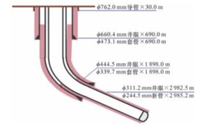
GA-E33P
Stratum Overview
The Graf block is primarily composed of Tertiary and Cretaceous strata, mainly consisting of limestone.
Drilling Parameters
The drilling parameters for each well section are shown in Table 1.
Table 1: Drilling Parameters of Each Drilling Section
| Wellbore Diameter (mm) | Drilling Pressure (kN) | Surface Rotary Speed (r·min-1) | Flow Rate (L·min-1) |
|---|---|---|---|
| 660.4 | <200 | 80~120 | 3,950 |
| 444.5 | <150 | ≤40 | 3,200~3,800 |
| 311.2 | <150 | ≤40 | 3,200~3,600 |
2 Description of the Accident Situation and Handling Process
The Φ444.5 mm section of Well Ga-E33P was drilled to a depth of 1,900 m and was completed midway. To facilitate logging and casing operations, a short tripping operation was performed to correct the wellbore.
The drilling tool assembly used was: Φ444.5 mm PDC + Φ244.5 mm × 1.5° drill collar + Φ395.0 mm stabilizer + Φ203.2 mm float valve + LWD + Φ203.2 mm short non-magnetic drill pipe + Φ308.0 mm stabilizer + two Φ203.2 mm drill pipes + Φ203.2 mm drill collar + ten Φ139.7 mm heavy drill pipes + Φ203.2 mm drill collar + Φ203.2 mm downhole shock tool + Φ203.2 mm drill collar + twelve Φ139.7 mm heavy drill pipes + Φ139.7 mm regular drill pipe. The drilling fluid had a density of 1.15 g/cm³, a viscosity of 40 s, and a pH value of 11.
When connecting the last stand to probe the well bottom, resistance was encountered, making it impossible to reach the bottom of the hole. The pump pressure dropped from 13.79 MPa to 12.41 MPa, the torque decreased from 10.8 kN·m to 8.1 kN·m, and the suspended weight was slightly reduced.
After pulling out, it was found that the downhole tool had broken at the internal thread of the Φ395.0 mm stabilizer. The downhole fish consisted of: Φ444.5 mm PDC × 0.45 m + Φ244.5 mm × 1.5° drill collar (with a built-in stabilizer of Φ438.0 mm) × 10.34 m + Φ395.0 mm stabilizer × 2.08 m, with a total length of 12.77 m and the fish top position at 1,877.23 m.
The fishing tool used was an external cone, and the fish was successfully retrieved. The fishing tool assembly included: 1.15 m external cone + Φ203.0 mm drill collar × 0.50 m + Φ203.0 mm drill collar × 0.80 m + Φ395.0 mm stabilizer × 2.10 m + Φ203.0 mm drill collar × 0.80 m + nine Φ139.7 mm heavy drill pipes + Φ203.0 mm drill collar × 0.80 m + Φ203.0 mm downhole shock tool × 9.70 m + Φ203.0 mm drill collar × 0.80 m + twelve Φ139.7 mm heavy drill pipes + Φ139.7 mm regular drill pipe.
3 Analysis of the Accident Causes
A schematic diagram of the drilling tool assembly and stress analysis is shown in Figure 2. The forces and moments acting on the drill string can be classified into three main types: ① Axial forces generated by drilling pressure, gravity, and friction; ② Torque; ③ Bending moments caused by wellbore curvature leading to deformation of the drill string. Each section of the drill string bears axial forces and torque, while the bent sections also experience additional bending moments.
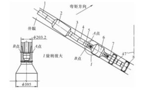
Drilling-tool-assembly
Figure 2: Stress Analysis of the BHA
1 – Φ203.0 mm drill pipe;
2 – Φ308.0 mm stabilizer;
3 – Φ203.0 mm short non-magnetic drill pipe;
4 – GE-LWD;
5 – Φ203.0 mm float valve;
6 – Φ395.0 mm stabilizer;
7 – drill collar;
8 – PDC bit.
The drill bit, drill collar, and Φ395.0 mm stabilizer have larger outer diameters and smaller clearances with the wellbore, resulting in greater stiffness and less bending deformation, which allows them to withstand smaller bending moments. In contrast, the components located above the Φ395.0 mm stabilizer, such as the float valve, LWD, short non-magnetic drill pipe, and Φ308.0 mm stabilizer, have smaller outer diameters and larger clearances with the wellbore. This results in lower stiffness and greater bending deformation, allowing them to withstand larger bending moments.
From the perspective of bending moment analysis, this section can be likened to a cantilever beam, where the “fixed end” is at the Φ395.0 mm stabilizer and the “free end” is at the Φ308.0 mm stabilizer. The closer one gets to the Φ395.0 mm stabilizer, the greater the bending moment experienced. Therefore, the internal thread of the Φ395.0 mm stabilizer bears the maximum bending moment, making it the most dangerous cross-section of the drill string.
Under the action of the bending moment, the inner side of the dangerous cross-section (Point A) experiences the maximum compressive stress. In contrast, the outer side (Point B) experiences the maximum tensile stress. As the drill string rotates, Point A gradually moves to Point B, during which the compressive stress decreases to zero, and the tensile stress increases to its maximum. When the drill string continues to rotate half a turn, Point A transitions from experiencing maximum tensile stress to maximum compressive stress, completing one cycle. Thus, for each full rotation of the drill string, the stress at Point A changes once per cycle.
Under prolonged loading, the stress concentration at the root of the threads is prone to fatigue failure and fracture. The greater the maximum tensile or compressive stress values, the faster the fatigue failure occurs. The varying axial forces, torque, vibrations, and bending moments combine to accelerate fatigue damage.
According to the mechanics of materials, the formula for calculating the maximum tensile (or compressive) stress is:
σmax = M / W
In the formula:
- σmax is the maximum tensile or compressive stress value.
- MM is the bending moment, which is related to the curvature (radius of curvature) of the drill string;
- WW is the section modulus for bending, which is related to the shape and size of the drill string cross-section.
The formula for calculating the section modulus for a circular cross-section is:
W = (πD3 / 32)[ 1 – (d / D)4 ]
In the formula:
- D is the outer diameter of the circular cross-section, and
- d is the inner diameter of the thread at the cross-section.
From equations (1) and (2), it can be seen that the larger the outer diameter of the circular cross-section, the larger the section modulus for bending. With a fixed (or relatively constant) bending moment, σmaxσmax will be smaller.
Based on the above analysis, the primary reason for the fracture phenomenon at the inner threaded end of the Φ395.0 mm stabilizer is its smaller outer diameter, which results in a smaller annular area formed with the root diameter of the internal threads. However, it experiences significant alternating stress, leading to fatigue cracking under a specific bending moment.
Typically, the Φ395.0 mm stabilizer used in a Φ444.5 mm wellbore has a 631 thread type at both ends, with a fishing neck outer diameter of 228.6 mm. According to the maximum stress analysis formula for the dangerous cross-section, with a constant bending moment, increasing the outer diameter of the stabilizer’s fishing neck can rapidly reduce the maximum tensile or compressive stress value at the inner threaded dangerous cross-section in a cubic relationship.
Additionally, due to the smaller fishing neck outer diameter of the Φ395.0 mm stabilizer, the joint threads inevitably produce sharp points and rounded corners during processing (according to API Spec 7-2, the thread profile for the 631 type is V-050, with a root point angle of 0.64 mm), leading to significant stress concentration at this location.
Consequently, the amplitude of the alternating stress (i.e., the maximum tensile or compressive stress value σmaxσmax) at the dangerous cross-section is excessively high, resulting in fatigue damage under alternating stress. The rate and extent of damage depend on the speed and magnitude of the stress variations.
Conclusions and Recommendations
Calculation Results:
The Φ395.0 mm stabilizer is the component in the Φ444.5 mm directional well drill string that experiences the most significant variation in stress and has the weakest strength, especially at the inner threaded end of the stabilizer, which is most prone to fatigue damage. During field operations, the stress conditions of the stabilizer should be altered by optimizing the drill string to prevent premature fatigue damage.
Increasing Outer Diameter:
Without changing the inner diameter of the tool, increasing its outer diameter can significantly enhance its strength. It is recommended to increase the outer diameter of the fishing neck and the outer diameter at the external thread of the Φ395.0 mm stabilizer from 203.2 mm to 210.0 mm or 215.9 mm, while keeping the thread type unchanged. If the outer diameter is increased to 229.0 mm or 241.0 mm and the thread type is changed to 730×731, it would be even safer.
Inspection:
Each time the tool is lowered into the well and after a period of use, it should undergo strict flaw detection to eliminate any quality defects and ensure safety.