42CrMo material has high strength, good toughness, and hardenability, with minimal quenching deformation and no obvious temper brittleness. After quenching and tempering treatment, it possesses a high fatigue limit and resistance to multiple impacts, along with good low-temperature impact toughness, making it widely used in industrial production.
During the production of a batch of 42CrMo cylinder forgings, ultrasonic testing was conducted after the rough machining process, as required by the process. It was found that one of the forgings had over-standard defects near the riser end, rendering it unusable. To identify the causes of these over-standard defects and propose corresponding improvement measures, a dissection analysis of the defective area of the cylinder forging was carried out.
Sample Preparation and Testing Methods
The manufacturing process for 42CrMo cylinder forgings includes:
EBT electric furnace smelting → LF refining → vacuum carbon deoxidation → vacuum casting → steel ingot pressing and trimming → upsetting → punching → elongating → expanding → finishing the blank → machining → ultrasonic testing → heat treatment
Defect Detection and Sample Preparation
After the machining process, ultrasonic testing revealed the presence of dense defects within a radial depth of 160 to 250 mm, in the area 500 mm from the riser end of the forging, with a maximum equivalent size of Φ4.7 mm. At the same time, the standard requirement states that the maximum defect size should not exceed Φ2 mm.
A low-magnification sample with a thickness of 20 mm was cut from the defective area at the riser end of the forging. After milling to a flat surface, the sample underwent a low-magnification hot acid etching test and a fracture test to observe its macro morphology.
Microstructural Analysis
A metallographic sample measuring 20 mm × 20 mm × 20 mm was taken from the macro defect area, and after processing, its microstructure was observed under a metallographic microscope. The defective area of the metallographic sample was analyzed using a KYKY2800 scanning electron microscope, and a spectrometer was used to observe crack traces.
Experimental Analysis
Macro Analysis
The macro morphology of the sample after low-magnification acid etching is shown in Figure 1. Multiple tiny cracks can be seen on the test piece, which are generally parallel in distribution. No other defects, such as porosity, looseness, or segregation, were observed.
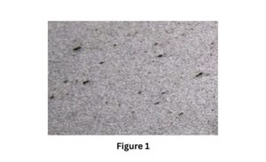
Macro morphology of the sample
The low-magnification sample was notched along the back of the defect and then fractured. The fracture morphology is shown in Figure 2. From Figure 2, it can be seen that the fracture is crystalline, with many minor black hole-like defects distributed on its surface
Based on the distribution and characteristics of the defects, the possibility of porosity defects can be excluded. A fragment was taken for quenching and tempering treatment, and after processing, it was notched and fractured again. The fracture exhibited significant plastic deformation, appearing fibrous; however, darker colored spots and hole defects were still present, thereby ruling out the possibility of white spot defects.
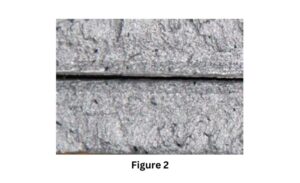
Low-magnification sample
Metallographic Analysis
A metallographic sample was taken from the low-magnification defect area for microstructural analysis. After grinding and polishing, the sample was observed under a metallographic microscope, revealing that the crack defects were inclusions, with a significant amount of oxide inclusions present at the tip and surrounding areas.
After etching with a 4% nitric acid ethanol solution, the sample was observed under the metallographic microscope, showing a microstructure of bainite with a grain size of grade 7, indicating that the structure is typical. The metallographic microstructure morphology of the sample is shown in Figure 3.
Scanning Electron Microscopy and Energy Dispersive Spectroscopy Analysis
Samples were taken from the defect area of the fracture test piece for electron microscopy analysis, with the morphological structure of the defect area shown in Figure 4. From Figure 4, it can be observed that the hole defects are cracked fracture surfaces, while other areas exhibit cleavage fracture modes. Upon magnifying the crack region, a large number of granular inclusions are seen aggregated on the fracture surface.
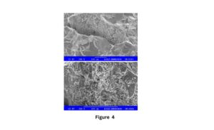
Electron microscopy
To clarify the nature of the inclusions on the fracture surface, energy dispersive spectroscopy was performed on the identified cracks and inclusions using a scanning electron microscope, as shown in Figure 5.
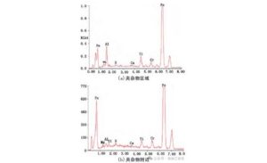
Energy dispersive spectroscopy 1
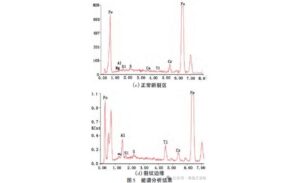
Energy dispersive spectroscopy 2
Semi-quantitative compositional analysis was conducted on the inclusion areas, areas near the inclusions, standard fracture zones, and the edges of the cracks, with the energy dispersive spectroscopy composition shown in Table 1.
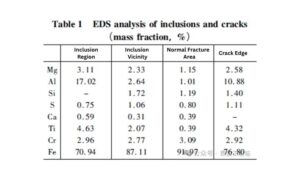
EDS Analysis
Analysis of Defect Causes
Identification of Defect Causes
From the results of the experimental analysis, it is evident that the excessive defects at the riser section of the cylindrical forging are large inclusions of aluminum oxide and titanium oxide, as well as cracks caused by these inclusions. During the smelting process of this cylindrical forging, aluminum deoxidation was primarily employed, resulting in the formation of deoxidation products that predominantly consisted of aluminum oxide.
Titanium Oxide Inclusion Formation
Additionally, to meet the mechanical performance requirements of the forging, approximately 0.030% titanium was added to the steel before it was smelted. During the vacuum pouring into the intermediate ladle, the molten steel came into contact with the atmosphere, resulting in the oxidation of titanium in the molten steel and the formation of titanium oxide inclusions.
Heat Loss and Slag Incorporation
Furthermore, a larger intermediate ladle was used during the production of molten steel, while the refining ladle had a smaller capacity for molten steel. This resulted in significant heat loss during the transfer between ladles, and the molten steel violently mixed with the refining slag.
The slag did not fully rise to the surface before reaching the lower limit of the pouring temperature, causing the refining slag to be poured into the steel ingot mold along with the molten steel. Ultimately, this led to the formation of annular, densely concentrated, excessive defects below the riser line in the forged cylinder.
Inclusion-Induced Cracking
The brittle inclusions of aluminum oxide and titanium oxide present in the riser area have significantly different physical and mechanical properties compared to the matrix. During the deformation process under stress, the brittle inclusions cannot deform the metal, resulting in plastic flow occurring around the inclusions in the more deformable steel matrix. This leads to stress concentration at the junctions and the formation of microcracks.
During the plastic deformation of the forging, the brittle aluminum oxide and titanium oxide inclusions are shattered along the main deformation direction, resulting in nearly parallel traces of inclusion cracks in the macroscopic morphology.
Improvement Measures
Large inclusions and cracks within the inclusions are the primary causes of excessive defects in the cylindrical forging, which occur during the steel ingot pouring process. The following improvement measures are proposed to address this issue:
- For smaller tonnage steel ladles, use smaller intermediate ladles during vacuum pouring to minimize excessive temperature loss during the transfer process. Using smaller intermediate ladles can result in a lower pouring temperature, affecting the fluidity of the molten steel and the rise of inclusions.
- Appropriately increase the pouring temperature of the molten steel to ensure that there is a surplus of 10°C above the upper limit of the pouring temperature after the steel enters the intermediate ladle. Increasing the pouring temperature of the molten steel will facilitate the smooth rising of inclusions to the surface after the transfer.
- After vacuum pouring into the riser section, appropriately reduce the pouring speed to avoid pouring refining slag into the steel ingot mold
